Process Description
Warning: Real fired heaters are very dangerous to operate. Explosions, fires and damaged tubing along with severe injury or even death to personnel can occur despite following approved operating procedures. Some heaters have minimal trip logic while others are highly instrumented to protect the heater from damage. In either case, experience has shown it is still possible to damage a heater from normal operations. The simulator will not necessarily replicate these scenarios because they highly depend on the type of heater and the particular fuel type, combustion air supply system, controls and interlocks. Therefore, operations practiced on the simulator should not be considered absolutely safe just because there were no dangerous conditions experienced. The simulator is intended to familiarize the operator with the basic principles of heat transfer by the combustion of fuel. Additional safety training on fired heaters is highly recommended in order to master the principles of safe operation.
Process Fluid Heating
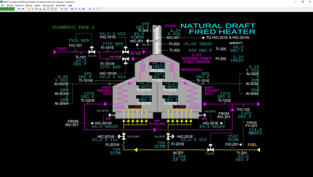
Process fluid from battery limits is fed to both the east pass and the west pass of the natural draft fired heater. The process fluid is first heated in tubes arranged in the convection section using hot flue gases leaving the radiant cells of the fired heater. These hot flue gases combine at the bridgewall which is the section that connects the radiant cells to the convection section. The process fluid is further heated in the east and west radiant cells before leaving the fired heater. The exiting process fluid streams are combined before flowing to the downstream process at battery limits.
Fuel Gas Firing
Fuel gas from battery limits is split into two lines which feed headers serving floor burners arranged on the bottom of the east and west radiant cells. The fuel gas is ignited and burned with combustion air entering from separate plenums serving each radiant cell. A wall divides the radiant cells up to the bottom of the bridgewall. The burned fuel in each cell primarily gives off heat to the process fluid flowing through the coils in the radiant cells via radiation. All the walls of the fired heater and the separating wall in the radiant section are covered with a fireproof lining that reflects heat reaching these walls back to the tubes and coils in the heater. The lining also insulates the heater walls to minimize heat loss to ambient.
Stack Effect, Flue Gas Flow and Draft
The hot flue gases rise through the radiant cells, combine in the bridgewall, flow up through the convection section and then rise up the stack on top of the fired heater. Even though the flue gas cools significantly as it passes up through the convection section, it is hot enough at the top of the convection section to so that the density of the flue gas is significantly lower than the density of the ambient air surrounding the heater. This density difference causes the hot flue gas to rise up the stack and is commonly known as the ‘stack effect’. It is the same principle that makes a hot-air balloon rise.
A large damper installed at the base of the stack permits adjustment of the flow rate of flue gas up the stack. To avoid complete blockage of flue gas flow when the damper is in the fully closed position, about 10% of the cross-sectional area of the damper is cut out. This prevents overpressuring of the fired heater.
The flow of flue gas up the stack due to the stack effect induces a slightly negative pressure difference from ambient at the bottom of the stack. This negative pressure difference is known as draft. Draft is higher (i.e., the pressure is more negative) as the flue gas temperature increases. Therefore, flue gas draft is normally highest in the radiant section, decreases at the bridgewall and is lowest at the top of the convection section.
Combustion Air
The negative pressure conditions of the radiant cells provide the driving force to pull ambient air from the air plenums into the radiant cells through air registers in the floor burners. Combustion air from ambient enters the east and west air plenums through large dampers and is drawn in through the air registers on each burner. The air dampers control the flow rates of combustion air into the plenums and through the air registers on the burners.
Instrumentation
Basic Controls
Process-side Instrumentation
The process feed flow is controlled by flow controller FIC-101. Flow to the east and
west passes can be adjusted by varying the positions of valves HIC-101E and HIC102W respectively. Process inlet temperature is indicated by TI-101. Process outlet
temperature is controlled by TIC-102 which modulates fuel flow to the burners. East
and west pass outlet temperatures are indicated by TI-102E and TI-102W
respectively. East and west pass crossover temperatures are indicated by TI-101E
and TI-101W respectively.
Fuel Gas Instrumentation
Fuel flow to the burners is controlled by temperature controller TIC-102 which is
cascaded to fuel flow controller FIC-201. Fuel flow to the east and west burners can
be adjusted by varying the positions of valves HIC-201E and HIC-201W respectively.
Fuel inlet temperature is indicated by TI-201.
Flue Gas Instrumentation
Temperatures in the east and west radiant cells of the furnace are indicated by TI301E and TI-301W respectively. Bridge wall temperature is indicated by TI-302.
Stack inlet and outlet temperatures are indicated by TI-303 and TI-304 respectively.
The draft in the east and west radiant sections of the furnace is indicated by PI301E and PI-301W respectively. Bridge wall draft is indicated by PIC-302. Stack draft is indicated by PI-303.
The stack damper position is controlled by HIC-301.
Volume percent oxygen in the stack gas is indicated by AIC-301.
The oxygen concentrations (volume %) of the flue gas in the east and west cells are indicated on AI-302E and AI-302W, respectively. The carbon monoxide concentrations (PPM) of the flue gas in east and west cells are indicated on AI-303E and AI-303W, respectively. The combustibles/hydrocarbon concentration (PPM) of the flue gas in east and west cells are indicated on AI-304E and AI-304W, respectively.
Advanced Controls
Combustion Air Instrumentation
Air flows into the plenums serving the east and west burners can be trimmed by
varying the positions of the respective air dampers HIC-301E and HIC-301W.
The ambient air temperature and pressure is indicated by TI-300 and PI-300 respectively.
The BURNER-E and BURNER-W switches act as both igniters and flame indicators. Note: These switches are not identified by tag on the main process schematic but are accessible on the simulator just above their respective burner assembly.
The draft in the furnace is controlled by bridge wall pressure controller PIC-302. The output of PIC-302 is cascaded to the setpoint of stack damper position controller HIC-301. Adjusting the stack damper position changes the flow of flue gas up the stack which, in turn, affects the draft in the fired heater. Normally, HIC-301 is in cascade mode and PIC-302 is in automatic mode.
The output of stack O2 controller AIC-301 is cascaded to the setpoints of both combustion air damper controllers HIC-301E and HIC-301W. If desired, differences between the east and west air flows are made by adjusting the ratio setting of HIC301E or HIC-301W. Normally, HIC-301E and HIC-301W are in cascade mode and AIC-302 is in automatic mode.