 |
 |
 |
 |
| Click to view scematic display A | Click to view schematic display B | Click to view schematic display C | Click to view schematic display D |
 |
|||
| Click to view schematic display E | |||
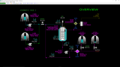
Process Description
Simtronics’ Continuously Stirred Tank Reactor (CSTR) with Tank Farm simulator enables detailed training of the operating principles of continuous liquid-phase reactors commonly found in the pharmaceutical, food, biochemical and fine chemicals industries. The CSTR with Tank Farm simulates the reaction between two aqueous feeds with the liberation of heat (exothermic reaction). The reactor vessel is jacketed and normally cools the reactor’s contents using cooling water. The CSTR with Tank Farm simulator can also be set up to make the reaction take in heat (endothermic reaction) if desired. In this case, the reactor’s jacket can be supplied with hot water to maintain the proper temperature inside the reactor.
The Tank Farm consists of two Feed Tanks, a Product Tank and an Off-Spec Tank. The Tank Farm allows realistic process training where inventory management is critical to operator decision making.
The CSTR vessel is stirred with a motor-driven agitator to ensure good mixing of the reactants.
The product from the CSTR is normally pumped to the Product Tank for intermediate storage and transfer for additional processing. The product can also be sent to the Off-Spec Tank to avoid contamination of the Product Tank with off-spec material. Off-spec product can be recycled to the CSTR or sent to disposal facilities at battery limits.
The CSTR with Tank Farm includes facilities for washing and purging the reactor vessel. This permits the simulator to be used for training good manufacturing practices that ensure high product purity.
A full range of operations can be learned and practiced on the CSTR with Tank Farm simulator. These include normal, startup, shutdown, and emergency shutdown procedures.
Purpose
The purpose of the CSTR with Tank Farm is to react two aqueous feeds to near completion on a continuous flow basis. The simulated feeds are a strong acid and a weak organic base. The reaction that takes place is the neutralization of the organic base by the addition of the strong acid. The reaction takes place with continuous flow in and out of the reactor. Feed and product storage tanks provide intermediate storage for managing variations in feed and product flows.
Importance
Continuously stirred tank reactors (CSTRs) are employed in higher volume product than can be attained with batch reactors. This is commonly found in the foods and fine chemicals industries. CSTRs are also important in the growing bio-fuels industry which employs reactors in a range of sizes from smaller volume enzyme production reactors to large volume continuous fermenters. Operators of these reactors must precisely follow recipes and operating procedures to ensure a high-quality product is obtained. Failure to do so often leads to a loss of profit to the operating company.
Major Equipment
The CSTR with Tank Farm process consists of the following major equipment:
- Reactant “A” Feed Tank, V-080
- Reactant “A” Feed Pump, P-080
- Reactant “B” Feed Tank, V-090
- Reactant “B” Feed Pump, P-090
- CSTR, R-101
- Reactor Condenser, E-101
- Vent K.O. Drum, D-101
- Reactor Pump, P-101
- Product Cooler, E-110
- Product Tank, V-111
- Product Pump, P-111
- Off-Spec Tank, V-112
- Off-Spec Pump, P-112
Process Overview
Two reactants labeled “A” and “B” are fed to respective storage tanks, V-080 and V-090, from battery limits. The reactants are pumped from their respective tanks to the CSTR R-101 by feed pumps P-080 and P-090, respectively.
R-101 uses agitation to ensure a uniform concentration of reactants and product throughout the CSTR. The normal residence time of liquid within R-101 is approximately 50 minutes. The reaction rate is moderately fast and conversion of the reactants is nearly complete within R-101. The fairly large residence time minimizes disturbances of product quality owing to minor feed flow and reactant concentration changes. Reaction heat is removed from R-101 through a water jacket enveloping most of the CSTR’s exterior wall. High reactor temperatures can lead to byproducts which will degrade the product quality.
The product mixture is pumped from R-101 by Reactor Pump P-101 to the Product Cooler E-110 and is then sent to the Product Tank V-111 for intermediate storage.
The residence time of V-111 allows for finishing of the reaction to take place. Product is pumped from V-111 to users at battery limits. In case there are upsets to the reactor, the product can be diverted to the Off-Spec Tank V-112 to avoid contaminating the Product Tank. Off-spec product can be recycled back to the CSTR R-101 or sent to disposal facilities at battery limits.
A wash water line is also provided to clean the CSTR at shutdown so that wash out procedures can be practiced.
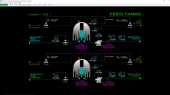
Feed Tanks
Two feed tanks, V-080 and V-090, are provided in the simulator to hold reactor feeds “A” and “B”. Both feed tanks are identically outfitted as follows:
- Feed supply line from battery limits
- Low pressure nitrogen line to the vapor space ensures a positive pressure and an oxygen-free environment within the tanks
- Vent line from the tanks to the atmospheric vent system
- Motor-driven centrifugal reactor feed pump (P-080 and P-090)
The tanks are identically sized and hold a working capacity of 1,000 gallons of liquid.
The bottom outlet of CSTR R-101 feeds Reactor Pump P-101. P-101 is a motor-driven centrifugal pump that moves reactor contents to the Product or Off-Spec Tanks in the storage area. P-101 can also be used to recirculate the reactor contents to the top of the reactor. This is useful when washing the reactor or if the unit is run in batch mode to eliminate settling of reactants at the bottom of the reactor. Recycle flow can also improve mixing of the reactants within R-101 especially if the agitator stops or its mixing blades are damaged during operation.
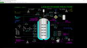
Reactor
The CSTR R-101 is fed by a short header which receives the following liquids:
- A solution containing reactant “A” from P-080
- A solution containing reactant “B” from P-090
- High-purity wash water
- Reactor recirculation from Reactor Pump P-101
- Off-spec recycle from Off-Spec Pump P-112
These liquids are charged to the top of R-101. The water is used for washing the process after the unit is shut down. The working capacity of R-101 is 1,000 gallons of liquid.
The solutions containing reactants will result in a reaction within R-101. The reactor contents are mixed with a motor-driven agitator consisting of paddles attached to the shaft of the agitator. A series of specially designed baffles on the inside walls of the reactor improve the mixing of the contents of the reactor, as well as maximize heat transfer with the circulating water in the exterior jacket.
The outside of R-101 is jacketed to allow cooling water or hot water to circulate against the wall of R-101. Cooling water is used for temperature control when the reaction releases heat. When the reaction absorbs heat, hot water is circulated. Water exiting the jacket is returned to battery limits.
Low pressure nitrogen is provided to the top of R-101 to ensure a positive pressure and an oxygen-free environment are maintained within the reactor. As the volume of liquid in R-101 changes, the corresponding vapor volume of R-101 will increase or decrease accordingly and result in a pressure change. Nitrogen, purged vapors and any vapors flashing from the liquid in the reactor are routed to the Reactor Condenser E-101 to condense any flashed vapors. E-101 is cooled using cooling water. Any condensate made in E-101 is separated in Vent Drum D-101 and returned by gravity back to R-101. Any net vapors from E-101 are routed to the atmospheric vent system.
The bottom outlet of CSTR R-101 feeds Reactor Pump P-101. P-101 is a motor-driven centrifugal pump that moves reactor contents to the Product or Off-Spec Tanks in the storage area. P-101 can also be used to recirculate the reactor contents to the top of the reactor. This is useful when washing the reactor or if the unit is run in batch mode to eliminate settling of reactants at the bottom of the reactor. Recycle flow can also improve mixing of the reactants within R-101 especially if the agitator stops or its mixing blades are damaged during operation.
Product & Off-Spec Tanks
Product Tank V-111
The Product Tank V-111 is a stainless-steel vessel and has the same liquid operating capacity as CSTR R-101. It is used to store the neutralized product from R-101 for feed to another reactor at battery limits. The holdup of the Product Tank provides production scheduling flexibility. At 50% level, the Product Tank has about 30 minutes of reserve capacity at the normal product delivery flow rate.
Product Pump P-111 Product Pump P-111 is a motor-driven centrifugal pump. Its design capacity is 15 GPM with a head of 30 PSIG.
Off-Spec Tank V-112.
V-112 is identical to V-111.
Off-Spec Pump P-112.
P-112 is identical to P-111.
Instrumentation
Feed Tanks
V-080
FIC-080 controls the flow rate of feed “A” from battery limits to V-080 by adjustment of the position of control valve FV-080.
LI-080 indicates the level of liquid in V-080.
PIC-080 controls the pressure inside V-080 by adjusting the position of the nitrogen supply valve PV-080A and the vent valve PV-080B. A split-range configuration ensures both valves are closed at 50% output of PIC-080. At 0% output, the nitrogen supply valve PV-080A is fully open and the vent valve PV-080B is closed. At 100% output, the nitrogen supply valve PV-080A is closed and the vent valve PV-080B if fully open.
Switch HS-080 operates the motor of Reactant “A” Feed Pump P-080.
AI-080 indicates the weight % of HCl in feed reactant A.
TI-080 indicates the temperature of feed “A” from P-080 to R-101.
V-080
FIC-090 controls the flow rate of feed “B” from battery limits to V-090 by adjustment of the position of control valve FV-090.
LI-090 indicates the level of liquid in V-090.
PIC-090 controls the pressure inside V-090 by adjusting the position of the nitrogen supply valve PV-090A and the vent valve PV-090B. A split-range configuration ensures both valves are closed at 50% output of PIC-090. At 0% output, the nitrogen supply valve PV-090A is fully open and the vent valve PV-090B is closed. At 100% output, the nitrogen supply valve PV-090A is closed and the vent valve PV-090B if fully open.
Switch HS-090 operates the motor of Reactant “B” Feed Pump P-090.
AI-090 indicates the weight % of organic base in feed reactant B.
TI-090 indicates the temperature of feed “B” from P-090 to R-101.
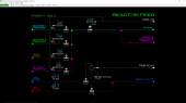
Reactor Feed
Reactor Feed Header
FIC-101 controls the flow of reactant A (hydrochloric acid solution) to R-101 by adjusting the opening of the reactant A valve FV-101.
FIC-102 controls the flow of reactant B (organic base) to R-101 by adjusting the opening of the reactant B valve FV-102.
FIC-103 controls the flow of water to R-101 by adjusting the opening of the water valve FV-103.
FIC-104 controls the flow of recycle product from V-112 to R-101 by adjusting the opening of the off-spec recycle valve FV-104.
Switch XV-101 resets (opens) or trips (closes) the solenoid valve XV-101 on the reactor feed line. Closing XV-101 blocks flow from FV-101, FV-102, FV-103 and FV-104 from entering R-101.
Jacket Water
TIC-103 (on Schematic 5) controls either the flow of cooling water (when jacket mode switch HS-103 is in the COOL position) or the flow of hot water (when HS-103 is in the HEAT position). Note the relationship between TIC-103 output and the cooling water supply valve position is direct (0% = closed) while the relationship between TIC-103 output and the hot water supply valve is reversed (0% = open). This is important when switching between modes. However, TIC-103 will function correctly in either mode.
When HS-103 is in the COOL position, the hot water supply valve is closed. When HS-103 is in the HEAT position, the cooling water supply valve is closed.
Reactor
E-101
HIC-103 adjusts the flow of cooling water through E-101.
TI-106 indicates the vapor temperature in R-101 entering E-101. TI-107 indicates its outlet temperature.
R-101
TIC-103 controls the temperature of R-101 by adjustment of either the flow of cooling water or the flow of hot water to the jacket of R-101.
TI-108A, B and C are located at various points in the reactor. TAH-108 indicates the highest of these three indicators and is used as a sensor for Reactor Interlock I-01 (trips at 120 DEG F).
LIC-101 controls the liquid level in R-101 by adjusting the position of control valve LV-101.
LAH-102 independently indicates the level in R-101 and trips the Reactor Interlock I-01 at 95% level.
PIC-101 controls the pressure inside R-101 by adjusting the position of the nitrogen supply valve PV-101A and the vent valve PV-101B. A split-range configuration ensures both valves are closed at 50% output of PIC-101. At 0% output, the nitrogen supply valve PV-101A is fully open and the vent valve PV-101B is closed. At 100% output, the nitrogen supply valve PV-101A is closed and the vent valve PV-101B is fully open.
PAH-102 also independently indicates the pressure inside R-101 and trips reactor interlock I-01 at 10.0 PSIG.
TI-104 indicates the temperature of the water leaving the jacket on R-101.
P-101
TI-105 indicates the temperature of reactor effluent to P-101.
Switch HS-104 operates the motor of Reactor Pump P-101.
FI-106 indicates the flow of liquid from P-101 through valve LV-101 to the Product Cooler E-110 and then to the Product and Off-Spec Tanks V-111 and V-112.
FIC-107 adjusts the position of FV-107 which recycles reactor liquid back to the feed header.
AI-102A indicates the weight % of HCl in R-101 effluent (reactant A). AI-101B indicates the weight % of organic base in R-101 effluent (reactant B).
Reactor
AI-101C indicates the weight % of neutralized organic in R-101 effluent.
Note that the analyzers will read zero when there is no liquid in R-101.
Product & Off-Spec Tanks
E-110
HIC-110 adjusts the position of cooling water valve HV-110.
TI-110 indicates the outlet temperature of reactor effluent leaving E-110.
V-111
Switch XV-111 opens and closes the feed isolation block valve XV-111 to V-111.
LI-111 indicates the level of liquid in V-111. TI-111 indicates the temperature of liquid in V-111.
PIC-111 controls the pressure inside V-111 by adjusting the position of the nitrogen supply valve PV-111A and the vent valve PV-111B. A split-range configuration ensures both valves are closed at 50% output of PIC-111. At 0% output, the nitrogen supply valve PV-111A is fully open and the vent valve PV-111B is closed. At 100% output, the nitrogen supply valve PV-111A is closed and the vent valve PV-111B if fully open.
Switch HS-111 operates the motor of Product Pump P-111.
FIC-111 controls the product flow to users by adjusting the position of control valve FV-111.
V-112
Switch XV-112 opens and closes the feed isolation block valve XV-112 to V-112.
LI-112 indicates the level of liquid in V-112. TI-112 indicates the temperature of liquid in V-112.
PIC-112 controls the pressure inside V-112 by adjusting the position of the nitrogen supply valve PV-112A and the vent valve PV-112B. A split-range configuration ensures both valves are closed at 50% output of PIC-112. At 0% output, the nitrogen supply valve PV-112A is fully open and the vent valve PV-112B is closed. At 100% output, the nitrogen supply valve PV-112A is closed and the vent valve PV-112B if fully open. Switch HS-112 operates the motor of Off-Spec Pump P-112.
FIC-112 controls the product flow to users by adjusting the position of control valve FV-112. >