 |
 |
 |
| Click to view schematic display A | Click to view schematic display B | Click to view schematic display C |
 |
 |
|
| Click to view schematic display D | Click to view schematic display E |
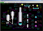
Process Description
The Simtronics SPM-2400 Fluidized Catalytic Cracking Unit (FCCU) Process Simulation includes a simulation of the Feed Preheat Exchanger Train, Slurry Settler, FCCU Converter (Reactor), Riser, Stripper, Regenerator, Air Blower, Air Heater, Main Fractionator, Light Cycle Oil (LCO) Stripper, Heavy Cycle Oil (HCO) Stripper, Heavy Naphtha (HN) Pumparound, LCO Pumparound, HCO Pumparound, Clarified Slurry Oil (CLO) Pumparound, Accumulator (Reflux Drum), Wet Gas Compressor, and High Pressure Separator (Suction Drum) systems.
In the Riser, heat from the catalyst first vaporizes the liquid feed and at the same time starts to crack the vaporized portion of the feed. The reaction mass is conveyed up the Riser to the Disengager Vessel where the catalyst and vapors are separated. After separating 99.99+% of the catalyst, the product vapors and steam leave the Disengager Vessel for the Main Fractionator.
The separated catalyst is transferred to the Stripper where entrained and absorbed hydrocarbons are removed. The stripped hydrocarbons and stripping steam leave the Disengager Vessel with the reactor products. The stripped spent catalyst then flows down the Spent Catalyst Standpipe to the Regenerator Vessel.
In the Regenerator, the spent catalyst is mixed with combustion air to burn the coke from the catalyst and any residual hydrocarbons from the Stripper. This restores the catalyst back to its optimum activity.
Air for the combustion process is provided by the Main Air Blower which is an axial flow compressor. A gas fired Air Heater is provided to heat the air during startup.
The reaction products from the Converter are passed to the Main Fractionator where they are separated into Wet Gas (Light Ends), Overhead Product termed Unstabilized Gasoline, FCC Gasoline, or Wild Cat Gasoline, Light Cycle Oil (LCO), Heavy Cycle Oil (HCO) and Fractionator Bottoms (CLO).
The Main Fractionator contains 18 trays. It is equipped with four pumparounds (HN, LCO, HCO, and Fractionator Bottoms), an Overhead Reflux System, and two Side Strippers for LCO and HCO products.
The vapors from the Converter enter the quench or bottom section of the Fractionator where they are cooled with the circulating bottoms pumparound which cascades down over the vapor entry point. This section of the tower also acts as a scrubber to prevent catalyst fines from passing up the tower into the more valuable "clean" products. Steam is injected to the base of the tower to keep the catalyst in suspension in the bottoms liquid.
The Fractionator bottoms product and recycle streams are drawn from the bottoms pumparound downstream of the Slurry Settler. The recycle is returned to the riser from the bottom of the Slurry Settler for recovery of entrained catalyst and is mixed with the fresh feed, while the product is taken from the top of the Slurry Settler. It is then cooled by several heat exchangers before going to storage.
At tray number 16 there is a draw off pan from which HCO product and HCO pumparound are drawn. The HCO product flows by gravity to the top of the HCO Stripper where stripping steam is used to remove the Light Ends, improving the flash point. The stripped HCO product is pumped to storage. The HCO pumparound is returned, after cooling, to the Fractionator on tray number 14.
The next streams to be drawn from the Main Fractionator, are the LCO Pumparound and LCO Product, which are drawn from tray number 10. The LCO product flows by gravity to the top of the LCO Stripper. Stripping steam is used to remove the light ends, improving the flash point. The stripped LCO product is pumped to storage. The LCO pumparound is returned, after cooling, to the Fractionator on tray number 8.
The final draw from the Main Fractionator is for Heavy Naphtha, which is drawn from tray number 2. The Heavy Naphtha pumparound is cooled and returned to the Fractionator on tray number 5.
The condensed Wild Cat Gasoline and Sour Water are separated by gravity in the Accumulator. Part of the gasoline is pumped back to the tower as reflux, and the rest goes to the High Pressure Separator. The Sour Water is drained to a disposal system.
The Wet Gas or vapors from the Main Fractionator Overhead Reflux Drum, are compressed by the Wet Gas Compressor (WGC). The Wet Gas Compressor is a two stage intercooled centrifugal machine driven by a steam turbine. The discharge vapors from the Wet Gas Compressor are routed to the High Pressure Condenser.
The combined function of the High Pressure Separator System is to reject the bulk of the light ends (C2-) from the feed streams, while recovering the C3= and heavier material for separation into saleable products. The vapor from the High Pressure Separator is passed to an untreated fuel gas system, while the Wild Cat Gasoline is passed to a Stabilizer Unit for further processing to a final product.
Instrumentation
The fresh feed to the FCCU is controlled by FIC-101. Feed block valves can be opened and closed with switches HV-101 and HS-101. HS-101 and HS-120 (recycle slurry flow, FIC-105) are automatically closed if the Main Air Blower (K-101) flow, FIC-100, is below 5 MSCFM or the Wet Gas Compressor (K-111) speed, SIC-110, is below 2000 RPM. The temperature of the fresh feed leaving the Preheat Train (E-112, E-113, Multiple Heat Exchangers, and E-101) is indicated by TI-100.
TIC-101 controls the Riser outlet temperature by sending hot regenerated catalyst to the Riser inlet through a slide valve, whose pressure differential is indicated by PDI-123. An additional Riser outlet temperature indicator (TI-101), with a wider range, is provided for start-up purposes.
After the gas and catalyst are separated in the Disengaging Drum, the spent catalyst is collected in the Stripper, whose temperature is indicated by TI-103, and sent to the Regenerator (R-102) by LIC-101 which modulates a slide valve, whose pressure differential is indicated by PDI-123. The Product Gas or vapor is sent to the Main Fractionator (T-111) through block valve HV-102.
Stripping Steam is modulated by FIC-107 while Lift Steam is modulated by FIC-103. A Reactor (R-101) Flare Valve (HIC-101) is provided for emergency conditions and shut-down purposes.
In the Regenerator, air is supplied from the Main Air Blower (MAB) through FIC-100. The Main Air Blower can be turned on and off with switch HS-100. The temperature of the Regenerator (TIC-102) controls the total amount of air to the Regenerator by resetting FIC-102, which vents air to the atmosphere. An additional Regenerator temperature indicator (TI-102), with a wider range, is provided for start-up purposes.
Fresh catalyst is fed to the Regenerator through HIC-301 while spent catalyst can be withdrawn from the Regenerator through HIC-302. Catalyst level in the regenerator is indicated by LI-102.
Torch Oil (FIC-106) and Fuel Gas (FIC-104) are used for warming up the Regenerator Bed during start-up. During start-up, the fuel gas is combusted directly in the Air Heater (H-101). The air temperature to the Regenerator is indicated by TI-124.
The primary Regenerator pressure controller is PDC-102. This controller maintains the pressure of the Regenerator (PI-101) at a constant differential above the Disengager pressure (PI-100) by controlling the position of the Regenerator Flue Gas Valve.
Flue gas compositions are displayed by AI-101, AI-102, and AI-103 in volume % O2, CO, and CO2 respectively.
The Quench Section temperature (TI-114) of the Main Fractionator is controlled by FIC-124 and controls overall quench flow to the Main Fractionator Bottoms by circulating bottoms liquid through Multiple Heat Exchangers. The Main Fractionator Bottoms Pump, P-114, which can be turned on and off with switch HS-114, provides the flow through the Bottoms pumparound system. Adjusting the amount of heat removed from the Fractionator by the quench, influences the temperatures in the Main Fractionator.
A small flow of Bottoms can be recycled to the Riser by diverting flow from the discharge of the product pumps (P-114). FIC-105 controls the Bottoms recycle flow rate. The recycle can be used to recover some catalyst, by gravity separation in the Slurry Settler (D-121), and prevent excessive catalyst accumulation in the Main Fractionator Column Bottoms (MFB).
The Slurry Settler is designed to remove catalyst, thus, reducing the ash content and raising the value of the MFB product stream. The MFB stream (CLO) is then passed through E-101, exchanging heat with the feed. The Bottoms product flowrate is controlled by LIC-114 cascaded to FIC-114.
A Start-Up Oil line is provided which is injected into the bottom of the Main Fractionator through block valve HV-114.
Stripping Steam (FIC-134) is injected in the Fractionator Bottoms preventing catalyst and coke from accumulating in the Fractionator Bottoms. In addition, by reducing hydrocarbon partial pressures, some light boiling components will be stripped from the Fractionator Bottoms liquid. Removing these lighter components increases the Bottoms product flash temperature.
Hot HCO flows by gravity, from tray number 16, to the HCO Stripper (T-113) through LIC-113, which controls the HCO Stripper's bottoms level. The HCO enters the Stripper at the top and flows downward over six trays. Stripping Steam, which improves the flash point by removing light ends, is introduced into the bottom of the Stripper through FIC-133. Steam and stripped light hydrocarbons flow from the Stripper back to the Fractionator above tray 14. The HCO product is pumped from the base of the Stripper by the HCO Product Pump P-113, which can be turned on and off with switch HS-113, to storage via E-113 where it is cooled. The HCO product flow to storage is controlled by FIC-113. The HCO draw temperature is indicated by TI-113.
HCO Pumparound, which is cooled by Multiple Heat Exchangers, is drawn from tray number 16 and returned to tray number 14. The pumparound is pumped by P-123, which can be turned on and off with switch HS-113, and is controlled by FIC-123.
Hot LCO flows by gravity, from tray number 10, to the LCO Stripper (T-112) through LIC-112, which controls the LCO Stripper's bottoms level. The LCO enters the Stripper at the top and flows downward over six trays. Stripping Steam, which improves the flash point by removing light ends, is introduced into the bottom of the Stripper through FIC-132. Steam and stripped light hydrocarbons flow from the Stripper back to the Fractionator above tray 8. The LCO product is pumped from the base of the Stripper by the LCO Product Pump P-112, which can be turned on and off with switch HS-112, to storage via E-112 where it is cooled. The LCO product flow to storage is controlled by FIC-112. The LCO draw temperature is indicated by TI-112.
LCO Pumparound, which is cooled by Multiple Heat Exchangers, is drawn from tray number 10 and returned to tray number 8. The pumparound is pumped by P-122, which can be turned on and off with switch HS-112, and is controlled by FIC-122.
Heavy Naphtha pumparound (drawn from tray number 2 and returned to tray number 5) is pumped by P-121, which can be turned on and off with switch HS-121, and is controlled by FIC-121.
The Main Fractionator's overhead pressure is indicated by PI-110 while the bottoms pressure is indicated by PI-114. A vent to flare valve (HIC-110) is provided for emergency operations and shutdown purposes.
The Main Fractionator Overhead Vapor flows through the Fractionator Overhead Cooler E-110, where the hydrocarbons are partially condensed. Cooling water to E-110 can be turned on and off with block valve HV-110. The condenser outlet temperature is indicated by TI-111.
The two phases (vapor/liquid) enter the Overhead Reflux Drum (Accumulator) D-110, where the gas and liquid separate and the condensed water (sour water) separates from the hydrocarbon liquid. Sour Water collects in the boot of the Overhead Reflux Drum, and is transferred to the Sour Water System for treating. LIC-111 maintains a constant sour water level.
The reflux is returned to tray 1 of the Main Fractionator from the Reflux Drum via pump P-110, which can be turned on and off with switch HS-110. The reflux flow is controlled by FIC-110 which is reset by TIC-110 to control the Tower Overhead Temperature. An additional overhead temperature indicator, TI-110, with a wider range, is provide for start-up purposes.
The Fractionator Overhead Temperature (TIC-110) is controlled to give the desired gasoline endpoint. Increasing the Fractionator Overhead Vapor temperature decreases the reflux flow (FIC-110) and permits higher boiling material to pass overhead into the Reflux Drum. This results in an increase in the gasoline endpoint. Decreasing the Fractionator Overhead Temperature will cause a decrease in gasoline endpoint. The level of hydrocarbons in the Reflux Drum is maintained by LIC-110 cascaded to FIC-109 which feeds the High Pressure Separator (D-111). The High Pressure Separator also serves as the suction drum for the Wet Gas Compressor (K-111).
The Wet Gas Compressor control system is composed of a speed controller SIC-110, suction pressure controller PIC-112, and an additional suction pressure controller, PIC-111, set higher than PIC-112, which vents excess gas from the compressor suction to the flare in the event that the Compressor cannot handle all the gas being routed to it. The Compressor speed controller SIC-110 modulates the Compressor speed by adjusting the steam flow to the turbine.
Compressor discharge flow is routed through E-111 and partially condensed by cooling water which can be turned on and off with block valve HV-111.
A fuel gas line to the suction of the Wet Gas Compressor is provided to pressure up the system during start-up. The fuel gas flow to the Compressor is modulated with HIC-111.
The flow of Wild Cat Gasoline Product (FI-120) is controlled by LIC-120 which maintains the High Pressure Separator's hydrocarbon liquid level, while PIC-120 controls the High Pressure Separator's pressure, by modulating the Light Ends Product flow (FI-125) to a fuel gas system.