 |
 |
 |
|
| Click to view schematic display A | Click to view schematic display B | Click to view schematic display C | |
Process Description
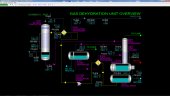
The Gas Dehydration Unit removes water vapor from produced gases destined for pipelines using tri-ethylene glycol (TEG) as the desiccating agent in the process. Removal of water vapor is essential to avoid the formation of slugs of water and hydrates (ice-like solids) in downstream operations. TEG remains completely in the liquid state at the normal operating conditions of the Gas Dehydration process. The so-called wet gas contacts lean, regenerated TEG in the Glycol Contactor T-601. The rich TEG is then regenerated in the Still Column T-611 by heating up the TEG with hot oil. The lean TEG is pumped back to Glycol Contactor. Dried gas produced from the Glycol Contactor contains a fraction of the water vapor concentration in the wet gas.
Instrumentation
Basic Controls: Gas/Glycol Exchanger E-601
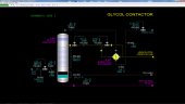
The flow of the wet gas to the bottom of the Glycol Contactor T-601 is controlled by FIC-601. AI-601 indicates the water content of the wet gas. Pressure and temperature of the wet gas stream are indicated on PI-601 and TI-601, respectively.
The temperature of the dry gas leaving the top of T-601 is indicated on TI-603. The temperature of the gas outlet stream from Gas/Glycol Exchanger E-601 is indicated on TI-604. AI-602 indicates the water content of the dried gas. The flow of the dried gas to battery limits is controlled by PIC-602.
The lean TEG circulation flow to T-601 is controlled by FIC-602.
The pressure drop across the trays of T-601 is indicated on PDI-603.
The level of rich TEG in the bottom of T-601 is controlled by LIC-601.
Basic Controls: Still Condenser E-611
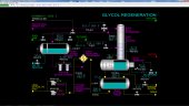
The temperature of the rich TEG going from Still Condenser E-611 to the Flash Separator D-611 is controlled by TIC-611 which adjusts the position of a three-way valve that bypasses rich TEG around E-611. Normally, this controller is in manual mode and the valve is lined up with 100% flow to E-611.
Basic Controls: Flash Separator D-611
The pressure of D-611 is controlled by PIC-611 which does split-range control of the fuel gas and flare valves:
- When PIC-611’s output is 0%, the fuel gas valve is wide open and the flare valve is closed
- When PIC-611’s output is 50%, both valves are closed
- When PIC-611’s output is 100%, the fuel gas valve is closed and the flare valve is fully open.
LIC-611 controls the level of rich TEG in D-611. LIC-612 controls the level of oil in the side sump of D-611.
Basic Controls: F-611A/B Glycol Filters
The pressure drop across F-611A/B Glycol Filters is indicated on PDI-612. PDI-612 will alarm in case of plugging that causes a high pressure drop across the filters.
Basic Controls: Rich/Lean Exchanger E-612
The temperature of rich TEG from Rich/Lean Exchanger E-612 is indicated on TI-613. The temperature of lean TEG from E-612 is indicated on TI-616.
Basic Controls: Still Column T-611
The temperature of the vapor leaving the top tray of Still Column T-611 is indicated on TI-612.
The pressure drop across the trays of T-611 is indicated on PDI-613.
Basic Controls: Reboiler E-613
The temperature of the lean TEG in Reboiler E-613 is controlled by TIC-614 which adjusts the setpoint of hot oil flow controller FIC-613.
The level of liquid in E-613 is indicated on LI-613. This level should normally be around 78 - 80%. The liquid in E-613 spills over a baffle at this level. Note that the baffle contains holes at the base to drain the liquid on the heating side of E-613 to Glycol Drum D-612 when the unit is shut down.
Basic Controls: Glycol Drum D-612
The level of lean TEG in Glycol Drum D-612 is indicated on LI-614. This level will fluctuate as other levels in the unit are changing, but should return to approximately the same indication when levels stabilize.
The temperature of lean TEG drawn from D-612 is indicated on TI-615.
Fresh glycol can be added to D-612 using HIC-611.
Glycol from D-612 can be sent to storage using HIC-612.
Basic Controls: Glycol Circulation Pumps P-611A/B
The motors of Glycol Circulation Pumps P-611A/B are operated by switches HS-611A/B, respectively. If a motor should fail, the switch of the affected switch will stay in the STOP state.