

Process Description
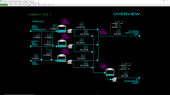
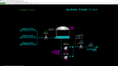
Crude Oil Blending System - Overview
Three different crude oils are delivered to the Crude Oil Blend Tank, T-121:
- West Texas Intermediate (WTI)
- North Sea Brent (NSB)
- United Arab Emirates Dubai (UAED)
Each of these crude oils is provided to the Crude Oil Blender with a range of properties
Normally,
- West Texas Intermediate is stored in Crude Tank #2, T-002
- North Sea Brent is stored in Crude Tank #3, T-003
- United Arab Emirates Dubai is stored in Crude Tank #4, T-004.
There are, however, crossover lines to ensure that the storage capacity can be fully utilized at all times, particularly in the event that specific crude oil(s) are not available.
The crude tanks T-002, T-003 and T-004 are able to feed a Blend Header, H-121, a Blend Tank, T-121, or both.
The blended crude oils are transferred from the refinery to large storage tanks. The storage tanks serve as inventory buffers so that the inventory may allow for fluctuations in the Refinery or the Product Blending System without immediately impacting the other unit(s).
Blended crude oil is delivered to either
- The Crude Distillation Unit via Blend Header, H-021
- Downstream Users via a Blending Tank, T-121, and Blend Tank Transfer Pumps, P-121A/B.
Crude Tank, T-002
Crude Tank #2, T-002, will contain West Texas Intermediate Crude. Crude Tank #2 Transfer Pumps, P-012A/B will transfer inventory from T-002 either to:
- the Blend Header, H-021
- the Blend Tank, T-121.
West Texas Intermediate Crude can also be delivered to Crude Tank #3, T-003, or to Crude Tank #4, T-004.
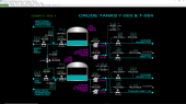
Crude Tanks, T-003 & T-004
Crude Tank #3, T-003, can receive either West Texas Intermediate Crude or North Sea Brent Crude (this tank will most often contain North Sea Brent Crude Oil). Normally, T-003 will accept only one of these crude oils (with crude blending occurring downstream). Crude Tank #3 Transfer Pumps, P-013A/B, will transfer inventory from T-003 either to:
- the Blend Header, H-021
- the Blend Tank, T-121.
Crude Tank #4, T-004 can receive West Texas Intermediate Crude, North Sea Brent Crude, or United Arab Emirates Dubai Crude (this tank will most often contain United Arab Emirates Dubai Crude Oil). Normally, T-004 will accept only one of these crude oils (with crude blending occurring downstream). Crude Tank #4 Transfer Pumps, P-014A/B, will transfer inventory from T-004 either to:
- the Blend Header, H-021
- the Blend Tank, T-121.
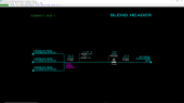
Blend Header, H-021
The Blend Header, H-021, receives crude oil from:
- Crude Tank #2, T-002
- Crude Tank #3, T-003
- Crude Tank #4, T-004
And delivers the blended crude oil to the downstream Crude Distillation Unit.
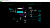
Blend Tank, T-121
The Blend Tank, T-121, receives crude oil from:
- Crude Tank #2, T-002
- Crude Tank #3, T-003
- Crude Tank #4, T-004
The crude oil is blended in the Blend Tank, T-121. The Blended Crude oil is transferred with Blend Tank Transfer Pumps, P-121A/B, to Downstream Users.
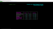
Feed & Distribution Properties
The schematic includes one table summarizing the characteristics of the crude oil supply (% Sulfur and API) and the use rate for each. In addition, the product delivery to the Crude Distillation Unit and Downstream Users are also characterized along with a corresponding use rate for each.
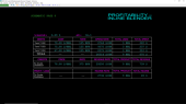
Profitability - Inline Blender
The schematic includes three tables which serve as a summary of the profitability for the inline blender product delivery to the Crude Distillation Unit.
The raw material cost from each crude storage tank, the usage rate, the spend rate, the total amount used, and the total amount spent from each crude oil tank is summarized in the Debit Table.
Similarly, the product price, product rate, revenue rate, total product and total revenue are summarized in the Credit Table.
The Profitability for crude oil distribution to the Crude Distillation Unit via the Inline Blender is summarized in the Profit/Loss Table.
Profitability – Blend Tank
The schematic includes three tables which serve as a summary of the profitability for the blend tank product delivery to Downstream Users.
The raw material cost from each crude storage tank, the usage rate, the spend rate, the total amount used, and the total amount spent from each crude oil tank is summarized in the Debit Table.
Similarly, the product price, product rate, revenue rate, total product and total revenue are summarized in the Credit Table.
The Profitability for crude oil distribution to the Downstream Users via the Blend Tank is summarized in the Profit/Loss Table.
Crude Oil Blending Profit & Loss
The schematic is a simple table showing the overall crude oil blend production and total income for the Crude Oil Blending System, covering both feed to the Crude Distillation Unit and Downstream Users.
IInstrumentation
Crude Tank, T-002
PI-002 measures the West Texas Intermediate (WTI) crude oil supply pressure. WTI is normally stored in Crude Tank #2, designated as Crude Tank #2, T-002. HS-002A will open or close XV-002A, the inlet valve to T-002. The crude oil flow into T-002 is measured by FI-002A. The level in T-002 is measured by LAH-002. Should LAH-002 exceed 90%, XV-002A will be forced closed to prevent the tank from overfilling. There is no other level control associated with this tank.
Crude Oil from T-002 is transferred downstream by Crude Tank Transfer Pumps, P-012A/B, using on/off switches HS-012A and HS-012B, respectively. Only one of these pumps is normally in service. Key properties of the crude oil from T-002 are measured by AI-002 (Weight % Sulfur) and DI-002 (API, which is a measurement representing density).
Crude Tank #2, T-002 product flow is controlled by:
- FIC-012A normally receives a setpoint from pressure controller PIC-012A for flow to Inline Blend Header H-021. Note that only one of PIC-012A, PIC-013A, or PIC-014A can be in AUTOMATIC at a time as they all effectively measure pressure at the same location.
- FIC-012B controls flow from T-002 to the Blend Tank, T-121.
If desired, West Texas Intermediate crude oil can be fed to Crude Tank #3, T-003 via XV-002B which is opened and closed by HS-002B with the corresponding flow rate displayed by FI-002B.
West Texas Intermediate crude oil can also be fed to Crude Tank #4, T-004, via XV-002C which is opened and closed by HS-002C with the corresponding flow rate displayed by FI-002C.
Note: The total flow rate of WTI crude oil to the three Crude Tanks is controlled upstream of the Crude Oil Blending System. Flow to any one of the tanks is stopped or started by closing or opening the appropriate isolation/transfer valve(s) as necessary. The total flow rate of WTI crude oil to the Crude Oil Blending System is reported on FI-002 which is provided on the table of Schematic #7.
Crude Tanks, T-003 & T-004
PI-003 measures the North Sea Brent (NSB) crude oil supply pressure. NSB is supplied to the Crude Blend Unit by opening XV-003 with HS-003. NSB is normally stored in Crude Tank #3, T-003. HS-003A will open or close XV-003A, the inlet valve to T-003. The NSB crude oil flow into T-003 is measured by FI-003A. If there is any WTI fed to T-003, the flow will pass through XV-002B which is opened and closed by HS-002B and displayed by FI-002B. The level in T-003 is measured by LAH-003. Should LAH-003 exceed 90%, XV-003A will be forced closed to prevent the tank from overfilling. There is no other level control associated with this tank.
Crude Oil from T-003 is transferred downstream by Crude Tank Transfer Pumps, P-013A/B, using on/off switches HS-013A and HS-013B, respectively. Only one of these pumps is normally in service. Key properties of the crude oil from T-003 are measured by AI-003 (Weight % Sulfur) and DI-003 (API, which is a measurement representing density).
Crude Tank #3, T-003, product flow is controlled by:
- FIC-013A which can receive a setpoint from pressure controller PIC-013A for flow to Blend Header H-021. Note that only one of PIC-012A, PIC-013A, or PIC-014A can be in AUTOMATIC at a time as they effectively measure pressure at the same location.
- FIC-013B controls flow from Crude Tank T-003 to the Blend Tank, T-121. FIC-013B normally will receive a set point from the ratio controller, RIC-013B.
As mentioned earlier, West Texas Intermediate crude oil can be fed to Crude Tank #3, T-003 via XV-002B which is opened and closed by HS-002B with the corresponding flow rate displayed by FI-002B.
PI-004 measures the United Arab Emirates Dubai (UAED) crude oil supply pressure. UAED is supplied to the Crude Blend Unit by opening XV-004 with HS-004. UAED is normally stored in Crude Tank #4, T-004. HS-004A will open or close XV-004A, the inlet valve to T-004. The UAED crude oil flow into T-004 is measured by FI-004A. If there is any WTI fed to T-004, the flow will pass through XV-002C which is opened and closed by HS-002C and displayed by FI-002C. Similarly, if there is any NSB fed to T-004, the flow will pass through XV-003B which is opened and closed by HS-003B and displayed by FI-003BC. The level in T-004 is measured by LAH-004. Should LAH-004 exceed 90%, XV-004A will be forced closed to prevent the tank from overfilling. There is no other level control associated with this tank.
Crude Oil from T-004 is transferred downstream by Crude Tank Transfer Pumps, P-014A/B using on/off switches HS-014A and HS-014B, respectively. Only one of these pumps is normally in service. Key properties of the Crude Tank T-004 are measured by AI-004 (Weight % Sulfur) and DI-004 (API, which is a measurement representing density).
Crude Tank #4, T-004, product flow is controlled by
- FIC-014A which can receive a setpoint from pressure controller PIC-014A for flow to Inline Blend Header H-021. Note that only one of PIC-012A, PIC-013A, or PIC-014A can be in AUTOMATIC at a time they all effectively measure pressure at the same location.
- FIC-014B controls flow to the Blend Tank, T-121. FIC-014B normally will receive a set point from the ratio controller, RIC-014B.
As mentioned earlier, West Texas Intermediate crude oil can be fed to Crude Tank #4, T-004, via XV-002C which is opened and closed by HS-002C with the corresponding flow rate displayed by FI-002C. North Sea Brent crude oil can be fed to Crude Tank #4, T-004 via XV-003B which is opened and closed by HS-003B with the corresponding flow rate displayed by FI-003B.
Note: The total flow rate of North Sea Brent crude oil to the two Crude Tanks, T-003 and T-004, is controlled upstream of the Crude Oil Blending System. Flow to any one of these tanks is stopped or started by closing or opening the appropriate isolation/transfer valve(s) as necessary. The total flow rate of North Sea Brent crude oil to the Crude Oil Blending System is reported on FI-003 which is provided on the table of Schematic #7.
Note: The total flow rate of UAE Dubai crude oil to the Crude Tank, T-004, is controlled upstream of the Crude Oil Blending System. Flow to T-004 is stopped or started by closing or opening XV-004 as necessary. The total flow rate of UAE Dubai crude oil to the Crude Oil Blending System is reported on FI-004 which is provided on the table of Schematic #7.
Blend Heater
Crude oils are combined in the Blend Header, H-021, before delivery to the Crude Distillation Unit.
The crude oil from storage tanks are combined in the H-021. The H-021 pressure is displayed as PI-021. The blended crude oil is characterized by:
- DI-021: API
- AI-021: Weight % Sulfur
The total crude oil flow sent to the downstream Crude Distillation Unit is controlled by FIC-022.
The pressure of the H-021 is indicated on PI-022. The pressure of the Blend Header is normally controlled by PIC-012A which adjusts the setpoint of WTI flow controller to the Blend Header, FIC-012A (see Schematic #3).
Blend Tank, T-121
Crude oil is combined in the Blend Tank, T-121, before delivery to downstream users.
The crude oil passes through XV-121 before entering the Blend Tank, T-121. Under normal circumstances, XV-121 is opened or closed by HS-121. The level in T-121 is measured by LAH-121. Should LAH-121 exceed 90%, XV-121 will be forced closed to prevent the tank from overfilling. There is no other level control associated with this tank.
Product from T-121 is transferred to the product pipeline via the Blend Tank Pumps, P-121A/B. These pumps are started and stopped by HS-121A and HS-121B, respectively. Only one of these pumps is normally in service.
Flow to Downstream Users is controlled by FIC-122. The feed pressure to downstream users is PI-122.