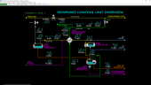
Process Description
The mixture of uncondensed feed gas, condensed hydrocarbons (NGL) and water-containing glycol from the tube-side of Feed Chiller (E-802) are separated in Low Temperature Separator (D-802) which is a three-phase separator. The gas phase separates out from the liquid and is piped from the top of D-802 to the Feed/Effluent Exchanger (E-801). The glycol/water is not miscible with the NGL and settles in to the boot of D-802 because it is more dense than the NGL. The glycol/water phase is taken from the boot to battery limits for removal of the water. The NGL floats above the glycol in the boot of D-802 and flows over a weir into the NGL recovery side. The NGL is taken off to storage and separation facilities at battery limits.
Cold conditioned gas from D-802 flows through E-801 to be warmed prior to flowing back to the pipeline through station isolation valve XV-805. In case the DPCU needs to be depressured, a line to a flare system at battery limits is provided upstream of XV-805.
The mainline station valve XV-806 is normally closed so that all the pipeline gas is routed to DPCU. All the station valves (XV-804, XV-805 and XV-806) are motor-operated valves. They are opened and closed by control logic so that operation is normally with XV-804 and XV-805 open and with XV-806 closed. The operator may bypass the DPCU manually which will cause the station valves to change from their normal positions to their opposite positions via the control logic. Interlock logic will automatically initiate a bypass of the DPCU and lock out the operator from introducing feed to the DPCU until the shutdown conditions are cleared.
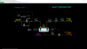
Inlet Separator
Natural gas from the pipeline passes through inlet station isolation valve XV-804, through a check valve and then into the Inlet Separator (D-801). A bypass valve HV-804 is provided to pressure up the DCPU prior to introducing high pressure natural gas into the unit. The bypass valve is automatically closed whenever XV-804 is detected to be fully opened.
Liquid contained in the feed is separated in D-801. A line from the bottom of D-801 takes the collected liquid off to Low Temperature Separator (D-802). Gas exiting the top of D-801 is sent to Feed/Effluent Heat Exchanger (E-801).
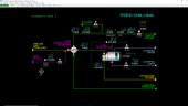
Feed Chilling
Lean glycol (essentially pure tri-ethylene glycol) from battery limits is injected through FV-802 into the gas stream from Inlet Separator (D-801). A special sparger and long mixing zone in the line to Feed/Effluent Heat Exchanger (E-801) promotes rapid absorption of a large fraction of the water vapor into the injected glycol. This will prevent icing during chilling of the gas in the DPCU. The water removal also protects the downstream pipeline from hydrates formation.
The gas and glycol mixture is cooled in E-801 using cold conditioned gas leaving Low Temperature Separator (D-802). The warmed conditioned gas from E-801 is normally sent to the pipeline through a check valve and then through station outlet isolation valve XV-805. In case the DPCU has to be depressured or if the DCPU unit is overpressured, conditioned gas can be sent to the flare system at battery limits through PV-805.
The cool gas/glycol mixture from E-801 is further cooled in the tubes of Feed Chiller (E-802) by boiling (evaporating) propane liquid on the shell side of E-802. As the feed mixture chills, heavier hydrocarbons in the feed condense on the tube-side. The chilled gas/NGL/glycol mixture then flows to Low Temperature Separator D-802. Propane liquid for E-802 is provided from the Propane Refrigeration System and evaporated propane is returned to the refrigeration system for recompression and liquefaction. The degree of hydrocarbon dewpoint depression in the DPCU can be changed by adjusting the outlet temperature of E-802.
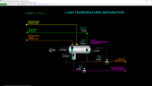
Low Temperature Separator
The mixture of uncondensed feed gas, condensed hydrocarbons (NGL) and water-containing glycol from the tube-side of Feed Chiller (E-802) are separated in Low Temperature Separator (D-802) which is a three-phase separator. The gas phase separates out from the liquid and is piped from the top of D-802 to the Feed/Effluent Heat Exchanger (E-801). The glycol/water is not miscible with the NGL and settles in to the boot of D-802 because it is more dense than the NGL. The glycol/water phase is taken from the boot to battery limits for removal of the water. The NGL floats above the glycol in the boot of D-802 and flows over a weir into the NGL recovery side. The recovered NGL is taken off to storage and separation facilities at battery limits.
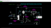
Propane Refrigeration System
Cold, low pressure propane vapor from Feed Chiller (E-802) passes through vapor isolation valve XV-101 and is combined with recycled warm propane vapor from the vapor space of the Propane Accumulator (D-102) that passes through Recycle Pressure Valve (PV-101). The combined vapor enters Compressor Suction Drum (D-101) to remove any liquid contained in the combined vapor prior to entering Propane Compressor (K-101). Normally there is no liquid present in the combined vapor.
The vapor from D-101 passes through a check valve at the inlet of K-101 which is a rotary screw compressor driven by Compressor Motor (KM-101) which has a variable frequency drive (VFD) electric supply. The rotary screw compressor is a dry type which means oil is not injected into the inlet of the compressor to ensure low-friction rubbing of the two helical screws to achieve efficient compression of the propane vapor while minimizing wear of the screws. To achieve precise alignment of the two helical screws without oil injection, a timing gear is used instead. The compression of propane vapor occurs in one single stage. This is possible with the high pressure ratio across the compressor since propane vapor has a lower temperature rise than most other refrigerants. The operating discharge temperature, therefore, is well under the limit at which mechanical damage to the compressor will occur, even under total recycle conditions at which the suction temperature will be at a maximum.
The two helical screws capture incoming propane vapor as they rotate and push the vapor through the space between the screws. The volume of the space between the screws continuously decreases up to the outlet resulting in a pressure increase of the vapor at the discharge. Because of the tight clearances between the screws, very little of the propane vapor back-flows through the screws. The gas leaves K-101, passes through another check valve and then enters Propane Condenser (E-101) which uses air to cool and condense the hot, high pressure propane vapor from K-101.
Condensed propane from E-101 is collected in D-102. The vapor above the liquid propane in D-102 is in equilibrium with the liquid and attains a pressure that is dependent on the temperature of the liquid propane. A recycle line through Recycle Pressure Valve (PV-101) to D-101 allows recycling vapor through K-101 when it is at minimum speed (30%) per the VFD. Liquid in D-102 is used to supply E-802 through liquid isolation valve XV-103.
Instrumentation
The temperature of feed gas from the pipeline is indicated on Feed Gas Temperature Indicator (TI-801). The position of station inlet isolation valve XV-804 is indicated on XI-804 which reflects the open and closed limit switches on the stem of XV-804. XI-804 will indicate as OPEN, TRVL or CLSD depending on these switches. XV-804 is controlled by station control logic (see Station Control below). The opening of startup bypass valve HV-804 is controlled by HIC-804. HIC-804 is locked in manual mode with an output of 0% whenever XV-804 is in the OPEN position. This ensures HIC-804 will not be left open in case there is a trip of the station which requires all pipeline gas flow to be stopped to the DPCU.
The pressure of Inlet Separator (D-801) is indicated on D-801 Feed Separator Pressure Indicator (PI-801). The level of liquid in D-801 is controlled by D-801 Feed Separator Level Controller (LIC-801) which adjusts the position of D-801 Feed Separator Level Valve (LV-801). The flow of liquid through LV-801 is indicated on D-801 Liquid Flow Indicator (FI-808). An independent level instrument D-801 Level High Alarm (LAH-801) is provided as a trip to the station interlock (see Interlock I-801 below).
The hydrocarbon dewpoint of the gas from D-801 is indicated on Dewpoint Feed Gas Analyzer Indicator (AI-801). This is the hydrocarbon dewpoint at the pressure of D-801. The water vapor concentration of the gas leaving D-801 is indicated on H20 Feed Gas Analyzer Indicator (AI-802). The gas flow leaving D-801 is indicated on Feed Gas Flow Indicator (FI-801).
Feed Chilling Controls and Instruments
The flow of lean glycol to the pipeline gas is controlled by Glycol to E-801 Flow Controller (FIC-802) which controls the position of Glycol to E-801 Flow Valve (FV-802). The temperature of feedgas leaving Feed/Effluent Exchanger (E-801) is indicated on E-801 Feed Out Temperature Indicator (TI-802). The temperature of the conditioned gas leaving E-801 is indicated on E-801 Condenser Gas Temperature Indicator (TI-805).
E-802 Feed Out Temperature Controller (TIC-803) controls the pipeline gas outlet temperature from Feed Chiller (E-802) by adjusting the setpoint of E-802 C3 Vapor Pressure Controller (PIC-802) which controls the pressure of the vapor space of the refrigerant side of E-802. In turn, PIC-802 adjusts the position of control valve E-802 C3 Vapor Pressure Valve (PV-802) which will affect the flow rate of vaporized refrigerant returned to the Propane Refrigeration System. Changing the pressure of the refrigerant side of E-802 will directly change the temperature at which the propane refrigerant boils in E-802.
E-802 Propane Level Controller (LIC-802) controls the refrigerant level in E-802 by adjusting the position of the E-802 Propane Level Valve (LV-802). The flow rate of refrigerant through LV-802 is indicated by E-802 C3 Liquid Flow Indicator (FI-803).
The pressure of conditioned gas leaving E-801 is controlled by Outlet Gas Pressure Indicator (PIC-805) which adjusts the position of Outlet Gas Pressure Valve (PV-805) going to flare. Normally PV-805 is closed as its setpoint is above the normally operating pressure of PIC-805.
The hydrocarbon dewpoint of the conditioned gas from E-801 is indicated on Dewpoint Conditioned Gas Analyzer Indicator (AI-805).
This is the hydrocarbon dewpoint at the pressure at the outlet of E-801. The concentration of water vapor of the conditioned gas is indicated on H20 Conditioned Gas Analyzer Indicator (AI-806). The flow of conditioned gas to the pipeline is indicated on Outlet Gas Flow Indicator (FI-807). The position of station outlet isolation valve XV-805 is indicated on XI-805 which reflects the open and closed limit switches on the stem of XV-805. XI-805 will indicate as OPEN, TRVL or CLSD depending on these switches. XV-805 is controlled by station control logic (see Station Control below).
Low Temperature Separator Controls and Instruments
The three-phase mixture of gas, NGL and glycol leaving Feed Chiller (E-802) is separated in Low Temperature Separator (D-802). The pressure of D-802 is indicated on D-802 Low Temperature Separator Pressure Indicator (PI-804). The temperature of cold gas leaving D-802 is indicated on D-802 Gas Out Temperature Indicator (TI-804). The level of NGL in the recovery side of D-802 is controlled by LIC-804 which adjusts the opening of control valve LV-804. The flow of NGL through LV-804 is indicated on FI-804. The interface level of between glycol and NGL in the boot of D-802 is controlled by LIC-805 which adjusts the opening of control valve LV-805. The flow of glycol through LV-805 is indicated on FI-805. LAH-806 indicates the level of NGL on the decant side of D-802 and is provided as a trip to the station interlock.
Propane Refrigeration System Controls and Instruments
Switch XV-101 controls the position of vapor isolation valve XV-101. Switch XV-101 is locked in the CLSD state in the event of a trip of the Propane Refrigeration System (see Interlock I-101 below).
The level of liquid in Compressor Suction Drum (D-101) is indicated on LAH-101 which is provided as a trip to the refrigeration system interlock (see Interlock I-101 below). The temperature of vapor leaving D-101 is indicated on TI-101.
The pressure of D-101 is controlled by Suction K-101 Pressure Controller (PIC-101). The output of PIC-101 controls both the position of Recycle Pressure Valve (PV-101) and the frequency of the VFD of Compressor Motor (KM-101) using a split-range calibration. Under normal operation, the output of PIC-101 directly controls the speed of KM-101 between 30% and 100% while PV-101 remains closed. When the output of PIC-101 falls below 30%, the frequency of the VFD will be held at 30% of power supply frequency and the position of PV-101 will increase to 100% opening at 0% controller output. The opening of PV-101 will occur at very low or no load operation of the Propane Refrigeration System.
The power to the VFD of KM-101 is controlled by KM-101 Motor Switch (HS-101). The speed of KM-101 is indicated on K-101 Speed Indicator (SI-101). The power used by motor KM-101 is indicated on KM-101 Power Indicator (JI-101).
Discharge K-101 Temperature Alarm High (TAH-102) indicates the discharge temperature of Propane Compressor (K-101) which is provided as a trip to the refrigeration system interlock (see Interlock I-101 below). Discharge K-101 Pressure Alarm High (PAH-102) indicates the discharge pressure of K-101 which is provided as a trip to the refrigeration system interlock (see Interlock I-101 below).
The motor of the fan for Propane Condenser (E-101) is controlled by switch E-101 Motor Switch (HS-102). The outlet temperature of E-102 is indicated on E-101 Outlet Temperature Indicator (TI-103).
The pressure of Propane Accumulator (D-102) is indicated on D-102 Accumulator Pressure Indicator (PI-103). The level of propane liquid in D-101 is indicated onD-102 Accumulator Level Indicator (LI-103). LI-103 will vary as conditions of pressure change and as the refrigerant level changes in Feed Chiller (E-802). Switch XV-103 controls the position of liquid isolation valve XV-103. Switch XV-103 is locked in the CLSD state in the event of a trip of the Propane Refrigeration System (see Interlock I-101 below).
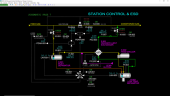
Station Control
The position of mainline station valve XV-806 is indicated on XI-806 which reflects the open and closed limit switches on the stem of XV-806. XI-806 will indicate as OPEN, TRVL, or CLSD depending on these switches. XV-806 is controlled by station control logic.
- XIC-801 is a switch that is used to change the position of motor-operated station valves XV-804, XV-805 and XV-806 as follows:
- When XIC-801 is placed in the RUN position, the station inlet and outlet valves XV-804 and XV-805 will be commanded to open and XV-806 will be commanded to close.
- When XIC-801 is placed in the STOP position, the station inlet and outlet valves XV-804 and XV-805 will be commanded to close and XV-806 will be commanded to open.
- It normally takes 30 seconds for the valves to fully open or close.
- If any of the valves do not attain their commanded position within 60 seconds, the respective sequence error alarm for the affected valves (XA-804, XA-805, XA-806) will sound.
- If a trip of the station occurs (I-801), XIC-801 will be locked in the STOP state until the interlock is reset.
The pipeline pressure at the inlet of XV-806 is indicated on Pipeline Inlet Pressure Indicator (PI-806A). The pressure at the outlet of XV-806 is indicated on Pipeline Outlet Pressure Indicator (PI-806B). The computed differential pressure across XV-806 is indicated on PDAH-806 and is provided as a trip to the station interlock (see Interlock I-801 below). The computed differential pressure across XV-804 is indicated on PDAH-804 and is provided as a trip to the station interlock (see Interlock I-801 below).
Monitoring of ambient combustible gas concentration is performed at the station. XA-881 will alarm if a significant gas concentration is detected. XAH-881 will alarm if excessively a high concentration of combustible gas is detected and is provided as a trip to the station interlock (see Interlock I-801 below).
Interlock I-101
This interlock protects the Propane Compressor (K-101) from mechanical damage due to excessive process conditions. It is a non-latched interlock and is activated by any of the following:
- Compressor discharge temperature Discharge K-101 Temperature Alarm High (TAH-102) exceeds 347 DEG F
- Compressor discharge pressure Discharge K-101 Pressure Alarm High (TAH-102) PAH-102 exceeds 290 PSIG
This interlock has the following effects:
- Stops power to Compressor Motor (KM-101)
- Locks KM-101 Motor Switch (HS-101) in the STOP state
- Locks switch XV-101 in the CLSD state
- Locks switch XV-103 in the CLSD state
- Causes an alarm on XA-101
The interlock automatically resets when all trip conditions are cleared. However, KM-101 must be manually restarted with HS-101 and the isolation valves XV-101 and XV-103 must be manually reopened.
Interlock I-801
This interlock protects the Dewpoint Control Unit process equipment from maloperation due to high pressure drop across the station valves or due to high liquid levels in the equipment. It is a latched interlock and is activated by any of the following:
- Inlet Separator Level Alarm High (LAH-801) exceeds 95%
- Low Temperature Separator Level Alarm High (LAH-806) exceeds 95%
- Pressure drop of inlet isolation valve PDAH-804 exceeds 145 PSIG
- Pressure drop of mainline valve PDAH-806 exceeds 145 PSIG
- Excessively high combustible gas concentration XAH-881
- I-801Trip/Reset Switch (HS-801) is manually placed in the TRIP state
This interlock has the following effects:
- Locks station control switch XIC-801 in the STOP state (see Station Control above for effects)
- Causes an alarm on XA-801
The interlock can be reset after all trip inputs are cleared by placing switch HS-801 into the OK state. Once the interlock has been reset, XIC-801 will be released.
NOTE: If the differential pressure across station inlet isolation valve XV-804 (PDAH-804) is too high for I-801 to be reset, pipeline gas must be brought into the station using startup bypass valve hand controller HIC-804 to bring the DPCU up to a sufficiently high pressure that will cause PDAH-804 not to be in alarm.