 |
 |
 |
 |
| Click to view scematic display A | Click to view schematic display B | Click to view schematic display C | Click to view schematic display D |
 |
|||
| Click to view schematic display E | |||
Process Description
In hydrocarbon processing units, over-pressurizing plant equipment can lead to equipment damage and risk to personnel. This risk is mitigated by releasing gas via pressure control and/or pressure relief valves. Ideally, the gas would be released into a pipeline for use by others. However, in most instances gas pipeline infrastructure is not available and the release gas is disposed to atmosphere by combustion with excess air with a flare system. The resulting combustion products, such as CO2 and H2O, lack the toxicity of the release gas and so can be normally be safely discharged to the surrounding environment.
Over the past several decades, government regulations have become increasingly more restrictive of flare releases into the atmosphere. While environmental restrictions vary substantially around the world, restrictions are most often related to:
- Thermal pollution
- Visual pollution – e.g., smoky flare emission
- Chemical pollution (both concentrations and total amount) in the form of:
- Hydrocarbons (as a result of incomplete or poor combustion)
- H2S (hydrogen sulfide)
- SO2 (sulfur dioxide)
- NOx (nitrous oxides)
Failure to comply with local environmental regulations will result in forced plant shutdowns, severe financial penalties, damaged reputation and lost production. It is for these reasons that operators must be intimately familiar with proper and safe flare operations so as to keep the facility operating in an environmentally compliant, cost efficient manner without interruption.
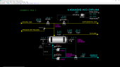
Simtronics’ Advanced Flare System program represents a typical Flare System with a flare header, knockout drum, knockout liquids pump system, water seal drum and a flare stack. In addition, there is a steam system which injects primary steam (normal flow conditions) or secondary steam (low flow conditions). The steam serves to promote overall flare mixing and to cool combustion gases. At low flow conditions, the steam also draws additional air into the stack via steam eductors to ensure complete combustion.
The hydrocarbon flare gas is from the following sources:
- Natural Gas (methane)
- Supplemental Gas (principally methane with some ethane, propane and butane)
- Process Release Gas (hydrocarbon stream with variable composition)
A full range of operations can be learned and practiced on the Advanced Flare System simulator. These include normal, startup, shutdown, and emergency shutdown procedures.
Flare gas enters the advanced flare system from any or all of the following:
- Natural gas (methane)
- Supplemental gas (methane with smaller amounts of ethane, propane and butane)
- Process unit release gas (hydrocarbon release of variable composition).
The natural gas is a cheap, clean source of fuel to keep the flare lit in case any release occurs from process units. The supplemental gas is supplied from the plant’s fuel gas system and is used to control the heating value of the flare release gas in case it contains significant concentrations of non-combustible compounds. This helps keep the flare stack hot during discharges in order to provide draft up the flare stack to maintain sufficient combustion air flow. The supplemental gas is also a backup in case of a loss of the natural gas.
The flare gases are combined in the flare header and routed to the Liquids Knockout Drum (D-951). Any accumulated liquids will be collected in D-951 and pumped to disposal with KO Liquids Pumps (P-951A/B). Flare gases in the vapor phase will exit the top of D-951 and flow to the Seal Drum (D-952).
Flare gas flows into the one side of the Seal Drum which is full of water to prevent air backflow from the Flare Stack to the flare header. Excess water from the seal side flows over a full baffle in the vessel and into the collection side. There is a continuous utility water flow through the Seal Drum to ensure it is always full on the seal side. Seal water pumps remove liquid from the collection side of the seal drum.
As the flare gas exits the seal drum it rises up the Flare Stack (FS-952) and is combined with Medium Pressure (MP) steam injected into distribution rings that surround burners at the top the Flare Stack. The steam promotes mixing of release gas with air to ensure complete combustion of the release gas. This also diminishes smoke emissions from the burners. The steam flow control system is designed to maintain optimal steam flow rates under low- and high-flow release gas conditions. This includes the use of eductors to draw in air with the steam under low-flow releases.
A pilot flame generator will keep the flare in a combustion state at startup and in case the main flame of the flare is extinguished.
Liquid KO Drum
The Liquids Knockout Drum (D-951) collects flare gas from three sources:
- Natural Gas
- Supplemental Gas
- Process Unit Release
The Liquids Knockout Drum operates at atmospheric pressure and receives these flare gases from battery limits.
The Liquids Knockout Drum will separate vapor and liquid, if any. The liquid will be pumped to disposal via Knockout Liquid Pumps (P-951A/B). Overhead vapor will pass on to the Seal Drum (D-952).
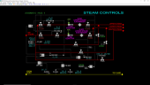
Steam Controls
Medium Pressure (MP) Steam is added to the flare gas to ensure complete mixing of the release gas with air and to cool the flare. MP Steam is generally added to the Flare Stack (FS-952) in proportion to the flare gas.
There are two modes of steam addition, primary and secondary steam. Under normal conditions, steam is added by primary steam addition. In primary mode, steam can enter the Flare Stack (FS-952) at the:
- Upper Steam Ring
- Lower Steam Ring
- Center Steam Ring
At low flare gas flow conditions (e.g., during startup), secondary steam addition is used. Secondary steam can enter the flare stack at the:
- Upper Steam Ring
- Lower Steam Ring
Secondary steam to the Upper Steam Ring will pass through a Steam Eductor (H-901) followed by the Upper Steam Exchanger (E-901). Secondary steam to the Lower Steam Ring will pass through a separate Steam Eductor (H-902) followed by the Lower Steam Exchanger (E-902).
At low flare flow conditions, the eductor serves to draw supplemental air into the flare stack. The subsequent heat exchanger uses steam to reheat the air/steam mixture which has been cooled by the addition of air.
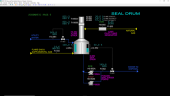
Seal Drum & Flare Stack
The total flare gas enters the left side of a divided Seal Drum (D-952) where it bubbles through the Seal Drum liquid. The Seal Drum removes any residual liquid phase hydrocarbons before entering the Flare Stack (FS-952). The left side of the Seal Drum is normally liquid full with excess water passing over a vertical baffle into the right side of the Seal Drum. The water in the right side of the seal drum is sent to disposal via the Seal Water Pumps (P-952A/B) with only one of these pumps normally in service.
A continuous flow of utility water will run through the Seal Drum. Utility water enters the left side of the Seal Drum under flow control. Utility water is removed from the right side of the Seal Drum under level control.
The Flare Stack combines the flare gas leaving the Seal Drum with steam and air to combust flare gas into CO2 and H2O in the Flare Stack. The Flare Stack also has a Pilot Flame Generator (X-955) to maintain favorable combustion conditions in the Flare Stack.
Instrumentation
Liquids Knockout Drum
Natural Gas to Flare Controller (HIC-960) adjusts the position of valve Natual Gas to Flare Hand Valve (HV-960) which will admit a small natural gas stream (100% methane) to the flare system. The natural gas flow is indicated on Natual Gas to Flare Flow Indicator (FI-960).
The upstream process unit may also release flare gas to the Liquids Knockout Drum via its pressure relief valve, PSV-402. The flow from the upstream process unit may be of variable composition.
Finally, the flare gas undergoes extensive analysis prior to entering the Seal Drum. One of the main purposes of the analysis is to determine the Lower Gas Heating Value (LGHV) of the total flare gas. The LGHV of the total flare gas is calculated from the composition measured both before entering the Seal Drum (AI-943, Schematic 5) and after combining with steam in the Flare Stack (AI-940). The lower of these two measured values (low selector AS-936) is the process value used by Flare Gas NGHV Analyzer Controller (AIC-936).
AIC-936 is cascaded to Supplemental Gas Flow Controller (FIC-936) which modulates the Supplemental Gas Flow Valve (FV-936). If needed, supplemental gas is added to the flare gas to raise the LGHV of the total flare gas. As previously mentioned, supplemental gas is a fixed composition (~48.7 wt % methane, ~19.6 wt % ethane, ~19.1 wt % propane and ~12.6 wt % butane).
The pressure of the Liquids Knockout Drum (D-951) is shown on D-951 KO Drum Pressure Indicator (PI-951) while its temperature is shown on Flare Gas Temperature Indicator (TI-931). The liquid level in D-951 is controlled by D-951 KO Drum Level Controller (LIC-951) which adjusts valve D-951 KO Drum Level Valve (LV-951). The flow of liquid condensate from the bottom of D-951 is measured by Disposal Flow Indicator (FI-951). Switches HS-951A and HS-951B are used to change the state of the motor for the Knockout Drum Liquids Pumps, P-951A and P-951B, respectively.
Overhead vapor flow from the Liquids Knockout Drum to the Seal Drum (D-952) is indicated on FI-953. The density of the overhead vapor is displayed by Flare Gas Density Indicator (DI-931).
Steam Controls
The flow rate of the total flare gas to the Seal Drum (D-952) is measured by both Low Flare Gas Flow Inidicator (FI-943) and High Flare Gas Flow Inidicator (FI-944). As accuracy of the total flare gas flow measurement is critical, two instruments are used to measure the flow. FI-943 is calibrated to measure low flow rates (and hence the instrument has a low instrument range) while FI-944 is calibrated to measure high flare gas flow rates (and has a much broader instrument range). A high selector, FS-945, selects between these two measurements.
The selected flare gas flow rate (FS-945), a volumetric flow measurement, is converted to a mass flow rate using the density measurement (DI-931).
MP Steam supply temperature is displayed on MP Steam Temperature Indicator (TI-901). The MP Steam supply pressure is displayed on MP Steam Pressure Indicator (PI-901).
As indicated earlier, MP Steam is supplied to the flare stack using either primary steam mode (under normal conditions) or secondary steam mode (under low flow conditions such as startup). The steam mode selection (primary=PRIM or secondary=SEC) is made with hand switch HS-901.
For primary steam mode, the steam/flare gas ratio is calculated based on the respective mass flow rates and displayed with the Primary Steam/Flare Ratio Controller (RIC-931). RIC-931 is a split range controller sending its output to both FV-931A and FV-931B.
In primary steam mode, steam is supplied to the:
- Upper Steam Ring via FV-931A which is manipulated by RIC-931
- Lower Steam Ring via FV-931B which is manipulated by RIC-931
- Center Steam Ring via FV-933 which is manipulated by FIC-933
The Primary Steam Flow Indicator (FI-931) used in the total steam/total flare gas includes each of the three steam supply paths mentioned above.
In secondary steam mode, which is not normally in service (used in low flare flow mode such as startup), steam is supplied to the flare as follows:
- Upper Steam Ring via Secondary Steam to Upper Ring Flow Valve (FV-901) which is manipulated by Secondary Steam to Upper Ring Flow Controller (FIC-901)
- Lower Steam Ring via Secondary Steam to Lower Ring Flow Valve (FV-902) which is manipulated by Secondary Steam to Lower Ring Flow Controller (FIC-902)
The steam flow rates measured by FIC-901 and FIC-902 are added together to provide the total secondary steam flow to the Flare Stack (FS-952). This calculated secondary steam flow is divided by the total flare gas flow to calculate the corresponding steam/flare gas ratio (wt/wt) used by Seondary Steam/Flare Ration Controller (RIC-901). RIC-901 is cascaded to both FIC-901 and FIC-902 to control the secondary upper steam flow and secondary lower steam flows, respectively.
To avoid controller windup which will result in sending a high flow of steam when switching between primary and secondary mode, the control system has the following functionality:
- When switch HS-901 is in the PRIM position, the control system locks secondary steam ratio controller RIC-901 in manual mode with an output of 0%. Also, FIC-901 and FIC-902 are locked in cascade mode and they will close their respective control valves FV-901 and FV-902.
- When switch HS-901 is changed from the PRIM to SEC position, RIC-901 will be placed into automatic mode on a one-shot basis.
- When switch HS-901 is in the SEC position, the control system locks primary steam ratio controller RIC-931 in manual mode with an output of 0%. This will close FV-931A and FV-931B.
- When switch HS-901 is changed from the SEC to the PRIM, RIC-931 will be placed into automatic mode on a one-shot basis.
The operator should ensure the desired setpoints of the steam ratio controllers RIC-901 and RIC-931 are properly set to ensure the least disruptive transition of the flare burners when changing the steam mode with HS-901.
Flare Monitoring
Prior to entering the Seal Drum (D-952), the total flare gas is analyzed with an online chromatograph to provide molar compositions of each component.
This composition analysis is critical to proper control of the advanced flare system as additional physical properties will be calculated (also known as inferred properties) from the above composition analysis.
The total flare gas molecular weight is directly measured by the analyzer system and is displayed by Molecular Weight Flare Gas Analyzer Indicator (AI-933). The Net Gas Heating Value (NGHV) of this stream is also directly measured by the analyzer system and is displayed on Flare Gas NGHV Analyzer Indicator (AI-943). It is us and passed on to the low selector (AS-936).
The various steam flow indications (see Schematic 4) are combined with the flare gas flow and release gas NGHV to obtain a calculated NGHV at the flare tip just before combustion, Flare Tip NGHV Analyzer Indicator (AI-940) (see Schematic 5), which is provided to low selector AS-936 (see Schematic 3). Controlling the calculated flare tip NGHV via Flare Gas NGHV Analyzer Controller (AIC-936) helps keep flare stack conditions (temperature, oxygen content) in a good operating range when steam and release gas flows are low.
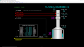
Indicators are provided in the flare stack to measure the concentration of critical pollutants which are present in trace quantities generally measured in PPM (parts per million). These analyzers are:
- AI-955 – H2S
- AI-956 – SO2
- AI-957 – NOx
Oxygen content just before flare gas is combusted is indicated on Molecular % 02 Analyzer Controller (AI-954). This is a theoretical calculation which gives the operator a guide on the simulator as to whether there is sufficient air to the flare or not.
Seal Drum & Flare Stack
The total flare gas flow is displayed by Flare Gas Flow Indicator (FI-945). This is the value calculated from the high selector FS-945 on schematic 4.
The Seal Drum (D-952), has a utility water feed supply to the left side of the drum. The valve which adjusts the utility water flow is FV-961 which is controlled by Seal Water Flow Controller (FIC-961). The water level in the left side of the Seal Drum is seen on Seal Water Level Indicator (LI-953). Normally, this indicates at 100% full. It should be checked regularly by briefly stopping utility water flow to verify that LI-953 responds.
The water level on the right side of the Seal Drum is controlled by D-952 Seal Drum Level Controller (LIC-952) and its corresponding valve, LV-952 which discharges water to disposal. The utility water flow rate is displayed on Water to Disposal Flow Indicator (FI-952).
The utility water pressure driving force to disposal is provided by the Seal Water Pumps (P-952A/B) which are started/stopped by HS-952A and HS-952B, respectively. Normally, only one of these two pumps will be in service.
Pilot Gas is introduced using HS-955. The pilot gas flow rate (a small flow rate) is seen on Fuel Gas to Pilot Flow Indicator (FI-955).
The Flare Stack (FS-952) also has several additional indicators to help monitor emissions and overall performance.
- Pilot Intensity Indicator (XI-955) monitors pilot intensity.
- Flame Intensity Indicator (XI-956) will show flame intensity.
- Flame Opacity Indicator (XI-957) will show flame opacity.
The Flare Stack also has redundant temperature measurements – Flare Stack Temperature Indicator (TI-955A/B).
Interlock I-951
Should the Liquids Knockout Drum (D-951) accumulate liquid, it must be pumped off to disposal with the Knockout Liquids Pumps (P-951A/B). Interlock I-951 performs much of the control related to liquids in D-951.
Under normal conditions, the Knockout Liquids Pumps will both be off. If the liquid level measured by LAH-951 reaches 30%, a high level condition is detected. The high level condition will
- Place D-951 Knockout Drum Level Controller (LIC-951) in AUTO mode
- Change the setpoint of LIC-951 to 40%
- Start pump P-951A.
Should the liquid level continue to increase and reach 60% which is considered a high-high condition, additional action will be taken by the interlock to
- Start pump P-951B.