 |
 |
 |
|
| Click to view schematic display A | Click to view schematic display B | Click to view schematic display C | |
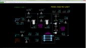
Process Description
Simtronics’ Reverse Osmosis (RO) process produces potable water from
brackish water. The brackish water is provided from battery limits.
Brackish water is purified by selective diffusion of water molecules
through a permeable membrane. The membrane will not pass most of the
impurities present in the brackish water. The purified water is
collected on the permeate side of the membrane and is filtered and
distributed to users. Some of the feed water and most of the impurities
(brine) are collected at the outlet of the feed side of the membrane and
are discharged to disposal facilities.
Simtronics’ Reverse Osmosis simulator consists of a single-stage Reverse
Osmosis unit. Real commercial units often employ two stages or double
pass systems or Reverse Osmosis system with concentrate recycle, but the
operating principles are still the same. The RO simulator represents a
once-through process so that the basic principles of the RO process may
be demonstrated without the added complexity of the recycle process.
A full range of operations can be learned and practiced on the Reverse
Osmosis simulator. These include normal, startup, shutdown, and
emergency shutdown procedures.
Reverse Osmosis
Brackish water from wells is filtered in Brackish Water Filters
F-101A/B. These are cartridge filters designed to remove any suspended
solids from the feed water. Suspended solids can easily plug the
permeable membranes in the Reverse Osmosis Unit. Either cartridge filter
can be taken out of service for maintenance.
Filtered feed water from F-101A/B is pumped to high pressure by brackish
water pumps P-101A/B. Normally only one pump is in operation.
The high pressure brackish water is fed to the Reverse Osmosis (RO) unit
X-101. The RO unit consists of a rack of 18 permeable membrane units
that operate in parallel. Each membrane unit consists of 20-foot long
spiral-wound membrane sheets within an 8-inch diameter housing. The
spirally-wound configuration permits a large cross-sectional area of the
membrane sheets to be installed in a relatively small volume.
The membrane sheets are specially fitted on each end of the housing to
segregate the feed side from the permeate (purified water) side. A feed
manifold routes the brackish water to the inlet sides of the membrane
units and two outlet manifolds collect the purified water and the brine
reject.
A high differential pressure across the RO membrane results in a large
osmotic pressure differential of water across the membrane. The membrane
is fabricated with material that will mainly permit smaller molecules to
diffuse through it. In brackish water, the smallest molecule is water.
The combination of high membrane cross-sectional area combined with a
high differential pressure across the membrane results in commercially
economic rates of water diffusion/transport through the membrane. Most
of the non-water molecules remain on the high pressure side of the
membrane, resulting in purification of the brackish water.
By design, a large fraction of the feed water flow does not permeate the
membrane to keep the impurity concentrations fairly low at the outlet
end of the high pressure side of the membrane. Otherwise, high
concentrations of impurities would increase their osmotic pressure and
force their way through the membrane. The excess water and impurities
(brine) are collected and routed to disposal facilities.
The purified water from the Reverse Osmosis unit X-101 is collected in
the purified water tank T-101.
The purified water is pumped from T-101 to distribution by purified
water pumps P-102A/B. Normally, only one pump is in service.
Prior to distribution, the purified water is further filtered in
cartridge filter F-102 to remove any solid particles and in activated
carbon filter F-103. Either product filter can be bypassed for
maintenance.
Instrumentation
Feed and RO Unit
The temperature of the brackish feed water is indicated on TI-101, the
pressure is indicated on PI-101 and the flow rate is indicated on
FI-101. AI-101 indicates the salinity of the brackish water in weight
percent. AI-104 indicates the conductivity of the brackish water in S/m
units (siemens per meter). The conductivity depends on the salt
concentration of the brackish water. AI-102 indicates the turbidity
(cloudiness) of the water entering the Brackish Water Pumps and is
measured in NTU (Nephelometric Turbidity Units). An NTU value less than
5 represents a very clear fluid, which is normally produced by the
Brackish Water Filters. Visually discernible cloudiness starts between
an NTU of 10 to 20. Values above 100 are obviously cloudy. AI-103 is the
pH of the brackish water. Values between 6.5 and 8.5 are acceptable for
the Reverse Osmosis Unit.
PDI-101A and PDI-101B indicate the pressure drop across the brackish
water filters F-101A/B. HIC-101A and HIC-101C control the block valves
of the brackish water filters F-101A/B. HIC-101B and HIC-101D control
the bypass valves of the brackish water filters F-101A/B.
The status of the brackish water pumps P-101A/B is indicated on switches
HS-101A/B, same switches can be used to start/stop the pumps. The
discharge pressure of brackish water pumps P-101A/B is indicated on
PI-102.
The brackish water flow from battery limits to the Reverse Osmosis Unit
X-101 is controlled by FIC-102. TI-102 indicates the brackish water
temperature at the entry of the Reverse Osmosis Unit X-101 while PDI-110
indicates the pressure drop across the Reverse Osmosis Unit X-101.
The flow rate of the reject brine is controlled by PIC-111 and is
indicated on FI-111.
The flow rate of the pressure of the purified water are indicated on
FI-110 and PI-110 respectively while HIC-110 controls the block valve at
the entry of the purified tank T-101. Normally HIC-110 is wide open to
keep a low product pressure and high differential pressure across the
unit. HIC-110 can be used to reduce the purified water production rate
at startup.
Purified Water and Product Filters
The water level in the purified tank T-101 is indicated on LI-120,
LAH-120 and LAL-120. LAH-120 and LAL-120 are also connected to
interlocks which are activated in case of high or low level,
respectively, in T-101.
AI-120 indicates the conductivity of the purified water in S/m units.
The status of the purified water pumps P-102A/B is indicated on switches
HS-102A/B, same switches can be used to start/stop the pumps. The
discharge pressure of purified water pumps P-102A/B is indicated on
PI-120.
PDI-120 and PDI-121 indicate the pressure drop across the cartridge
filter F-102 and the activated carbon filter F-103, respectively.
HIC-120A controls the block valve of the cartridge filter F-102 while
HIC-120C controls the block valve of the activated carbon filter F-103.
HIC-120B controls the bypass valve of the cartridge filter F-102 and
HIC-120D controls the bypass valve of the activated carbon filter F-103.
FIC-120 controls the flow rate of the produced purified water to the
users. The temperature of the produced purified water is indicated on
TI-120.
Interlock I-101
Interlock I-101 protects the purified water tank T-101 from overflow.
I-101 is activated when the level of LAH-120 is more than 90%. I-101
will remain active anytime LAH-120 is more than 90% and will stop the
brackish water pumps P-101A/B. I-101 will automatically reset when
LAH-120 indicates lower than 90%. However, the brackish water pump
P-101A/B must be manually started after the interlock resets.
Interlock I-102
Interlock I-102 protects the purified water pumps P-102A/B from
cavitation. I-102 is activated when the level of LAL-120 is less than
10%. I-102 will remain active anytime LAL-120 is less than 10% and will
stop the purified water pumps P-102A/B. I-102 will automatically reset
when LAL-120 indicates higher than 10%. However, the purified water pump
P-102A/B must be manually started after the interlock resets.