Process Description
OTU Process Description
Overview
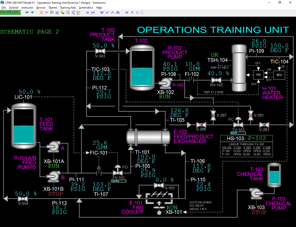
The H.O.T. Model 01 is a straightforward process design that circulates water from the feed tank (T-101) through product tank (T-102) and back to the feed tank. A level control scheme is provided on T-101 to control the level. The feed from the feed tank (T-101) is heated to a desired temperature range by means of the feed/product exchanger (E-102). A temperature control scheme controls the inlet water temperature to T-102. The water from the product tank (T-102) is heated by the water heater (H-101) and is used as the heat medium for feed/product water exchanger (E-102) to heat the feed water. Upon leaving the feed/product exchanger (E-102), the product water is cooled by air fan cooler (E-101) before returning to the feed tank (T-101).
Feed Tank (T-101)
The H.O.T. Model 01 feed tank (T-101) is a 300-gallon polyethylene tank with a maximum design temperature of 125 ºF. Make-up water is supplied to the feed tank (T-101) by an offsite water source; the water supply is routed through a gate valve located on the product return line inlet to the feed tank (T-101). On the simulator, the unit is already filled, so the fill line is not simulated. The feed tank (T-101) is equipped with a removable screwed cover located on top of the tank.
Feed Pumps (P-101 A/B)
The H.O.T. Model 01 unit feed pumps (P-101 A/B) pump the water from the feed tank (T-101) to the product water tank (T-102). The feed pumps (P-101 A/B) take suction off the feed water tank (T-101) bottom suction line and pump the feed water through the feed water flow control valve (FV-101). The flow control valve regulates the flow of feed water through the feed/product water exchanger (E-102) before entering product tank (T-102).
During normal operations, one feed pump will operate and the other will be in standby mode for use when the primary pump is out of service. The feed pumps (P-101 A/B) are equipped with the necessary valving on the suction and discharge lines to operate both pumps in parallel or in series mode for training exercises (only parallel mode is simulated).
The feed pump (P-101 A/B) suction and discharge lines are equipped with liquid filled pressure gauges to monitor pumps during routine operations and for energy control isolation exercises (local gauges are not simulated). The feed pumps (P-101 A/B) are equipped with “Y” strainers in the suction lines for pulling and cleaning for training exercises (the strainers are not simulated; faults are provided to simulate a loss of head due to strainer plugging). The feed pumps (P-101 A/B) are also equipped with a minimum flow line with a manually operated globe valve for pump protection in the event the feed water flow is restricted (this is not simulated; the equipment is assumed to be correctly operated in the field).
Feed/Product Exchanger (E-102)
The primary function of the feed/product exchanger (E-102) is to heat the H.O.T. Model 01 unit feed water before it enters the product tank (T-102). The feed water is routed through the tube side and the heat medium (product water) is routed through the shell side of the feed/product water exchanger (E-102).
The feed/product exchanger (E-102) is equipped with vents, drains and a bypass on each side of the heat exchanger so it can be taken in and out of service for training exercises (this is not simulated). The tube side of the feed/product exchanger (E102) is equipped with the necessary piping to provide back flushing capability for training exercises (this is not simulated). The feed/product exchanger (E-102) piping and valving arrangement allows the student to isolate and pull the tube bundle for inspection and cleaning (this is not simulated).
Product Tank (T-102)
The H.O.T. Model 01 unit product tank (T-102) is a 300 gallon polyethylene tank with a design maximum temperature of 125º F. The product tank (T-102) is equipped with a magnetic level sight glass (LG-102) for level monitoring (the level gauge is simulated, and its indication is graphically provided on Schematic 2 as a level bar inside the vessel outline). The level gauge column has isolation and vent valves to take the level column out of service for training exercises and maintenance repairs (not simulated). The product tank (T-102) is equipped with a removable screwed cover with vent located on top of the tank.
There are two means of controlling the feed water temperature to the product tank (T-102). The temperature control valve (TV-103) can be routed to the heat medium stream, or directly into the water leaving the feed/product water exchanger (E-102) to the product tank (T-102). On the simulator, a switch HS-103 is provided to line up TV-103 to either of these configurations. There are two sources of cooling agent that can be routed through the feed water temperature control valve (TCV-103); cool feed water from the feed water header upstream of FV-101 (Feed Water Flow Control Valve) or product water from the product water header upstream of H-101 (Water Heater).
Product Pump (P-102)
The H.O.T. Model 01 unit product pump (P-102) is used to pump the product tank (T-102) water to the feed tank (T-101). The product pump (P-102) pumps the water through the water heater (H-101), the shell side of the feed/product exchanger (E102) and the fan cooler (E-101). The product pump (P-102) takes suction off of the product tank (T-102) bottoms suction line. The suction line of the product water pump (P-102) is equipped with duplex strainers (S-101 A/B) to demonstrate the difference between a clean and a fouled strainer (the strainers are not simulated; a fault is provided to simulate a loss of head due to strainer plugging).
The product pump (P-102) suction and discharge lines are equipped with liquid filled pressure gauges to monitor pump during routine operations and for energy control isolation exercises (these are not simulated). The product pump (P-102) is also equipped with a minimum flow line with a manually operated globe valve for pump protection in the event the product water flow is restricted (this is not simulated; the equipment is assumed to be correctly operated in the field).
Water Heater (H-101)
The primary function of the water heater (H-101) is to heat the product water from the product tank (T-102) to provide a heat medium for the feed/product exchanger (E-102) shell side. H-101 is electrically heated.
Fan Cooler (E-101)
The fan cooler (E-101) cools the product water from the product/feed exchanger (E-102) before entering the feed tank (T-101). The fan cooler (E-101) is powered by 480 volt 3 phase.
The fan cooler (E-101) is also equipped with vents, drains and a bypass so it can be taken in and out of service for training exercises (only the bypass is simulated).
Chemical Tank (T-103)
The chemical tank (T-103) is a 20 gallon polyethylene tank with a design maximum temperature of 125º F. The chemical tank (T-103) is equipped with a chemical injection pump (P-103) with a graduated calibration gauge column on the tank so that the student can adjust the specific metered flow rate into the process (metering is not simulated; the pump can only be turned on/off; only gross material effects on system water inventories in T-101, T-102 and T-103 are simulated). Chemical tank (T-103) has the necessary valving to isolate and drain the tank (these are not simulated). This will allow the student to take the tank in and out of service.
Chemical Injection Pump (P-103)
The chemical injection pump, P-103, is designed to intermittently charge chemicals to the water circulation loop at a rate of 0.8 gph with a discharge pressure of 150 psig (the pumped fluid is assumed to be pure water on the simulator).
Sample Station
The sample station provides the necessary valving to collect samples for testing/analysis. This includes a totally close loop sample station with sample bomb for high level sampling and vent for low level sampling. The H.O.T. Model 01 unit sample station and piping is made of 100% stainless steel (the station is not simulated).
Control Panel (Electrical/Instrumentation)
The Hot Skid requires a 3 phase, 480VAC, 60Hz, 100A supply as well as a 1 phase, 220VAC, 60Hz, 80A supply.
- Loads requiring 480VAC:
- Water Heater (H-101) Heater Elements
- Fan Cooler (E-101) Fan Motor
- Loads requiring 220VAC:
- Water Heater (H-101) Thermostat Control.
- Pump Motors: Feed Water Pumps (P-101 A/B), Product Pump (P-102), Chemical Pump (P-103)
- Siemens S7-200 PLC (Programmable Logic Controller): Feed Water Flow Indicator Controller (FIC-101), Product Water Flow Indicator (FI-102), Feed Water Tank Level Indicator Controller (LIC-101), Water Heater Outlet Temperature Indicator Controller (TIC-102) and Feed Water Temperature Indicator Controller, (TIC-103)
(The control panel is not simulated. However, faults are provided to allow training on a loss of power to any simulated motor and to the Water Heater H-101. These faults can be grouped to simulate a 220V and a 480V power dip or outage.)
Utilities
Instrument air header (Clean dry air to be supplied by customer at a pressure of 90-130 PSIG) (the air supply pressure is provided as a fault on the simulator, and it can be adjusted quickly or slowly to affect the positions of the two control valves FV-101 and TV-103).
Instrumentation
Overview
Feed Tank (T-101)
The feed tank level indicator controller (LIC-101) controls the feed tank (T-101) level. The feed tank level indicator controller (LIC-101) is cascaded to the feed water flow indicator controller (FIC-101). The feed water flow indicator controller (FIC-101) regulates the feed water flow control valve (FV-101); the feed water flow control valve (FV-101) will open when the feed tank (T-101) level increases above setpoint and will close when the level goes below setpoint.
Feed Pumps (P-101 A/B)
Switches XB-101A and XB-101B are used to start and stop the Feed Pumps. During normal operations, one feed pump will operate and the other will be in standby mode for use when the primary pump is out of service.
The pressure of the discharge line from P-101A/B is indicated on PI-111.
Feed/Product Exchanger (E-102)
The flow controller FIC-101 regulates the flow of feed water through the feed/product water exchanger (E-102) before entering product tank (T-102) by adjusting the position of control valve FV-101. This control valve is a fail-open type of valve and will fully open upon a loss of instrument air pressure. On the simulator, the position of FV-101 is indicated using a horizontal bar indication under the valve on Schematic 2.
PI-105 indicates the pressure of the feed line downstream of FV-101. The temperature of the feed to E-102 is indicated on TI-101.
The temperature of hot product water to E-102 is indicated on TI-105. The outlet temperature of the product water from E-102 is indicated on TI-106. The pressure of the product leaving E-102 is indicated on PI-110.
Product Tank (T-102)
The feed water temperature indicator controller (TIC-103) controls the feed water temperature to the product tank (T-102). The feed water temperature indicator controller (TIC-103) regulates the feed water temperature control valve (TCV-103).
There are two means of controlling the feed water temperature to the product tank (T-102). The temperature control valve (TV-103) can be routed to the heat medium stream, or directly into the water leaving the feed/product water exchanger (E-102) to the product tank (T-102). The feed water temperature control valve (TV-103) will open when the feed water temperature indicator controller (TIC-103) setpoint increases above setpoint and will close when the temperature goes below setpoint. There are two sources of cooling agent that can be routed through the feed water temperature control valve (TV-103); cool feed water from the feed water header upstream of FV-101 (Feed Water Flow Control Valve) or product water from the product water header upstream of H-101 (Water Heater).
On the simulator, the position of TV-103 is indicated using a horizontal bar indication under the valve on Schematic 2.
Switch HS-103 is provided on the simulator to change the lineup of valves around TV-103 according to the routing described above. Switch HS-103 can be set to a state of “P-102” so as to align product from P-102 through TV-103 or it can be set to a state of “P-101” so as to align feed from P-101 through TV-103. A table is provided on schematic 2 to illustrate the switch’s function.
The pressure of the feed to T-102 is indicated on PI-112. Local globe valve V-343 is simulated to permit adjusting the pressures of the feed line downstream of FV-101.
On the simulator, the level gauge LG-102 is simulated and presented on schematic 2 as a graphical bar overlaid on T-102 so that the water level can be monitored.
Product Pump (P-102)
The motor of product pump (P-102) is controlled by switch XB-102. The discharge pressure of P-102 is indicated on PI-108.
Water Heater (H-101)
The flow of water from P-102 to H-101 is indicated on FI-102. Field globe valve HV102 is simulated to allow adjustment of this flow.
The temperature indicator controller (TIC-104) controls the water heater (H-101) water outlet temperature by adjustment of the average heat rate to the heater. This average rate is accomplished by a sequencer on the real unit which turns the power to the heater on and off for a time determined by the output of TIC-104. The simulator accomplishes the same with a more direct calculation.
The water heater (H-101) outlet is equipped with a high temperature and a low flow alarm and shutdown. The temperature indicator controller (TIC-104) will alarm when the heater outlet temperature reaches 155 ºF and will shutdown the heater when the temperature rises to 165 ºF; the product flow indicator (FI-102) will alarm when the flow reaches 3 GPM and will shutdown the heater when the flow falls to 2 GPM.
The outlet pressure of product from H-101 is indicated on PI-109.
Fan Cooler (E-101)
The fan cooler (E-101) motor is controlled by switch XB-101. It will turn on automatically if the PV of water heater (H-101) outlet temperature controller TIC104 exceeds 115 ºF.
The outlet temperature from E-101 after the bypass return connection is indicated on TI-107. The pressure out of E-101 is indicated on PI-113. The bypass globe valve V-163 is provided on the simulator to allow adjustment of the temperature of the product sent to the feed tank (T-101).
Local globe valve V-054 is simulated to permit adjusting the pressure of the product line downstream of water heater H-101 to the outlet of E-101.
Chemical Tank (T-103)
The level of chemical tank (T-103) is indicated on LG-104 and presented on Schematic 2 as a level bar overlaid on T-103.
Chemical Injection Pump (P-103)
The motor of chemical injection pump (P-103) is controlled by XB-103.