Process Description
Introduction
Simtronics’ Total Trainer simulator enables training for the operation of basic process equipment such as pumps, tanks, heaters and coolers. The simulator also allows training of process controls and interlock systems.
The simulated process is a digital replica of a skid-mounted trainer. This allows significant cost savings since the real equipment does not have to be purchased, installed and maintained.
Startup and shutdown of the equipment can be learned and practiced on the Total Trainer simulator. Also, thirteen faults representing abnormal equipment and instrument conditions are provided with the simulator so that problem identification and recovery can be practiced.
The rest of this manual describes the simulated Total Trainer process and provides detailed operating procedures and exercises which can be used for learning basic process plant operations.
Process Flow Overview
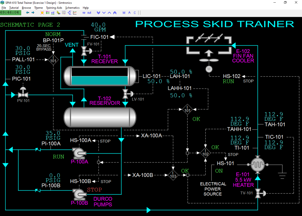
Circulating liquid (water) is contained in two storage tanks, T-101 and T-102. Both tanks are vented to atmosphere to eliminate pocketing of air in the tanks.
Receiver T-101
The first tank, Receiver, T-101, collects water circulated through the control valve of flow controller FIC-101 and cooled water from Fin-Fan Cooler, E-102. The water from each of these two streams mixes in T-101.
The level of water in T-101 is controlled by level controller LIC-101. This controller will normally adjust the opening of the gravity drain valve from T-101 to the second tank, Reservoir T-102. Alternatively, LIC-101 can be cascaded to flow controller FIC-101 by placing FIC-101 into cascade mode. In this situation LIC-101 will adjust both the opening of the gravity drain valve and the setpoint of FIC-101.
Reservoir T-102
Reservoir T-102 receives water circulated through the control valve of pressure controller PIC-101 and water drained by gravity from Receiver T-101. The level of water in T-102 is not controlled and there is no instrumentation to see the level.
T-101 and T-102 are identical. The process is inventoried with enough water so that both tanks are normally 50% full. Therefore, when the level is high in T-101 the level in T-102 will be correspondingly low and vice-versa.
Circulation Pumps P-100A/B
Water from Reservoir T-102 is supplied to Circulation Pumps P-100A and P-100B which are driven by electric motors. These pumps are centrifugal types so that flow will vary with discharge pressure. Normally, one pump is in operation. Each pump is fitted with a check valve on the discharge line so that flow from one pump cannot be recirculated through the other pump when it is not in operation.
Hand switches HS-100A and HS-100B are provided to start and stop each pump. Each hand switch is designed to always indicate the true operating status of its electric motor drive.
Water Flow
Water pumped by P-100A/B is split into three lines:
- The first line is routed to T-101 through the control valve of flow controllerFIC-101.
- The second line is routed to T-102 through the control valve of pressure controllerPIC-101.
- The third line is routed to Electric Heater E-101 through the control valve of temperature controller TIC-101
Instrumentation
Basic Controls
The circulation pumps P-100A/B are operated by hand switches HS-100A/B. The discharge pressures of the pumps are indicated on PI-100A/B. If a pump is stopped it will be alarmed on XA-100A/B.
The pressure of the water distribution piping is controlled by PIC-101 which adjusts the flow rate of water to T-102. The controller will alarm when the pressure drops below 10 PSIG. PALL-101 activates at 5 PSIG and will cause a trip of the circulation pumps on low pressure via interlock I-101.
To start the circulation pumps, the signal from PALL-101 must be momentarily bypassed. Hand switch BP-101P is provided for this purpose. When set to the BYPS (bypass) state, PALL-101 will be bypassed for 20 seconds allowing one of the circulation pumps to be started.
The main circulation flow to T-101 is controlled by FIC-101. An alarm will sound if the flow drops below 10 GPM. FIC-101 normally operates in automatic mode. To demonstrate cascading two controllers, FIC-101 may be placed into cascade mode to receive its setpoint from LIC-101. In this mode, LIC-101 will adjust the setpoint of FIC-101 and the opening of the gravity drain valve to T-102 until a suitable condition is found that keeps the level at the setpoint value.
LIC-101 normally controls the level of T-101 by adjusting the opening of the gravity drain valve to T-102. There are three independent level instruments from LIC-101: LAH-101, LAHH-101 and LG-101. LAH-101 will alarm when the level in T-101 goes above 70%. LAHH-101 will alarm and activate interlock I-101 when the level in T-101 goes above 80%. This will also alarm on ESD-101. LG-101 represents an independent local gauge reading from the opposite side of T-101.
HS-101 switches the power supply to E-101.
The outlet temperature of E-101 is controlled by TIC-101 which adjusts the flow through the Electric Heater. TAH-101 independently measures and alarms when the outlet temperature is above 130 DEG F. TAHH-101 will activate interlock I-102 if the temperature climbs above 140 DEG F. This interlock will cause a stoppage of the power to the Electric Heater.